Page 11 of 17
Re: Digger's '69 Build Thread
Posted: Sun Jan 20, 2019 11:46 pm
by Digger
Re: Digger's '69 Build Thread
Posted: Mon Jan 21, 2019 6:24 am
by Strike2
Wow I envy your knowledge on fitting that motor in the engine bay, I wouldn't even know where to begin.
Looking forward to the progress!
Re: Digger's '69 Build Thread
Posted: Mon Jan 21, 2019 7:03 am
by ZOSO
Strike2 wrote:Wow I envy your knowledge on fitting that motor in the engine bay, I wouldn't even know where to begin.
Looking forward to the progress!
Sawsall..... that's how you start.
Re: Digger's '69 Build Thread
Posted: Mon Jan 21, 2019 8:37 am
by Jesus_man
For having half the liters, it's amazing how big that motor still is!
Re: Digger's '69 Build Thread
Posted: Mon Jan 21, 2019 8:17 pm
by Kinder
Wow, that is great side by side shot, I didnΓÇÖt expect the motor to be so symmetrically square. My 4BT is more tall than wide, IΓÇÖll have to dig up the dimensions so we can compare them.
Re: Digger's '69 Build Thread
Posted: Mon Jan 21, 2019 11:05 pm
by Digger
I had a few people comment on size difference, so I threw the intake and induction back on the 5.8 and used MS Paint to bring the two engines level with each other for relative size comparison.

The Explorer front dress and induction system is more compact, but you get the idea.
Re: Digger's '69 Build Thread
Posted: Tue Jan 22, 2019 10:50 am
by dbasile
Wow! It is hard to believe that there is little size difference between the 2. The pic with the engines on the floor make the diesel look huge.
Can't wait to see the progression.
Re: Digger's '69 Build Thread
Posted: Tue Feb 05, 2019 11:33 pm
by Digger
Made a little more progress. I've been busy measuring and modelling for the transmission adapter. Axis Industries has a few of these and frankly, they've distilled their design down pretty well. My first attempt looked way too much like their's. So much so, I considered trying to contact them again to discuss this project. BUT I had an idea today that simplifies the adapter and gets it away from looking like a copy.
First thing I had to do was mock up the business end of the Windsor block and make sure crank and bell housing dimensions were correct. Then I mated that to a section of the R2.8 and starting hashing out how to mate the two. This is the end result:
Here's the whole setup with a very quick and dirty transmission package.
CAD Mockup 01.jpg
Adapter with Ford flywheel
CAD Mockup 02.jpg
Without flywheel
CAD Mockup 03.jpg
Exploded View
CAD Mockup 04.jpg
I need to have a template LASER cut at work to confirm all the hole placements. After that, we'll be making chips.
Re: Digger's '69 Build Thread
Posted: Wed Feb 06, 2019 7:31 am
by Strike2
Digger,
Your build make me feel like I'm working with poster board & large crayons
Re: Digger's '69 Build Thread
Posted: Wed Feb 06, 2019 7:37 am
by Jesus_man
ok, so the red part is the r2.8 and then the default SW colored part is your adapter? I am pickin' up what you're layin' down!
remind us again, you are sticking with a ZF5 correct?
Re: Digger's '69 Build Thread
Posted: Wed Feb 06, 2019 8:16 am
by phyler
Strike2 wrote:Digger,
Your build make me feel like I'm working with poster board & large crayons
Says the guy who is kicking tail on his own build. You both make me feel lacking in my skills.
Sent from my Pixel 2 using Tapatalk
Re: Digger's '69 Build Thread
Posted: Wed Feb 06, 2019 8:39 am
by Digger
Jesus_man wrote:ok, so the red part is the r2.8 and then the default SW colored part is your adapter? I am pickin' up what you're layin' down!
remind us again, you are sticking with a ZF5 correct?
Yes, the red part is the tailhousing of the R2.8 with the crank flange and starter nose mocked in. Referencing the tailhousing only reduced burden on the computer.
Yes, I'm sticking with the ZF5. I like it. I dorked-out on a spreadsheet comparing the ZF wide ratio to a ZF close ratio variant. Not much practical difference for towing at highway speeds. 4th is the same, 5th is nearly the same and third is close enough. If I have to drop below 3rd while towing, I've got problems.
The nice thing about the R2.8 is max torque is at 1800 rpm, so if I'm cruising at 75 mph (2500 rpm) and start losing speed due to a hill or wind, the engine will keep pulling harder until I drop below 1800 rpm.
Re: Digger's '69 Build Thread
Posted: Wed Feb 06, 2019 8:49 am
by Jesus_man
Gotcha. Such an awesome setup it will be!!
How many parts will the adapter be? I assume one for the flywheel as well?
Re: Digger's '69 Build Thread
Posted: Wed Feb 06, 2019 9:37 am
by Digger
phyler wrote:Strike2 wrote:Digger,
Your build make me feel like I'm working with poster board & large crayons
Says the guy who is kicking tail on his own build. You both make me feel lacking in my skills.
Sent from my Pixel 2 using Tapatalk
Yeah, no joke!
I love the collective skill set and drive that members of this club have. Can you imagine what could be done with a common shop space and 100k!
Re: Digger's '69 Build Thread
Posted: Sun Mar 31, 2019 1:51 pm
by Digger
Time for update.
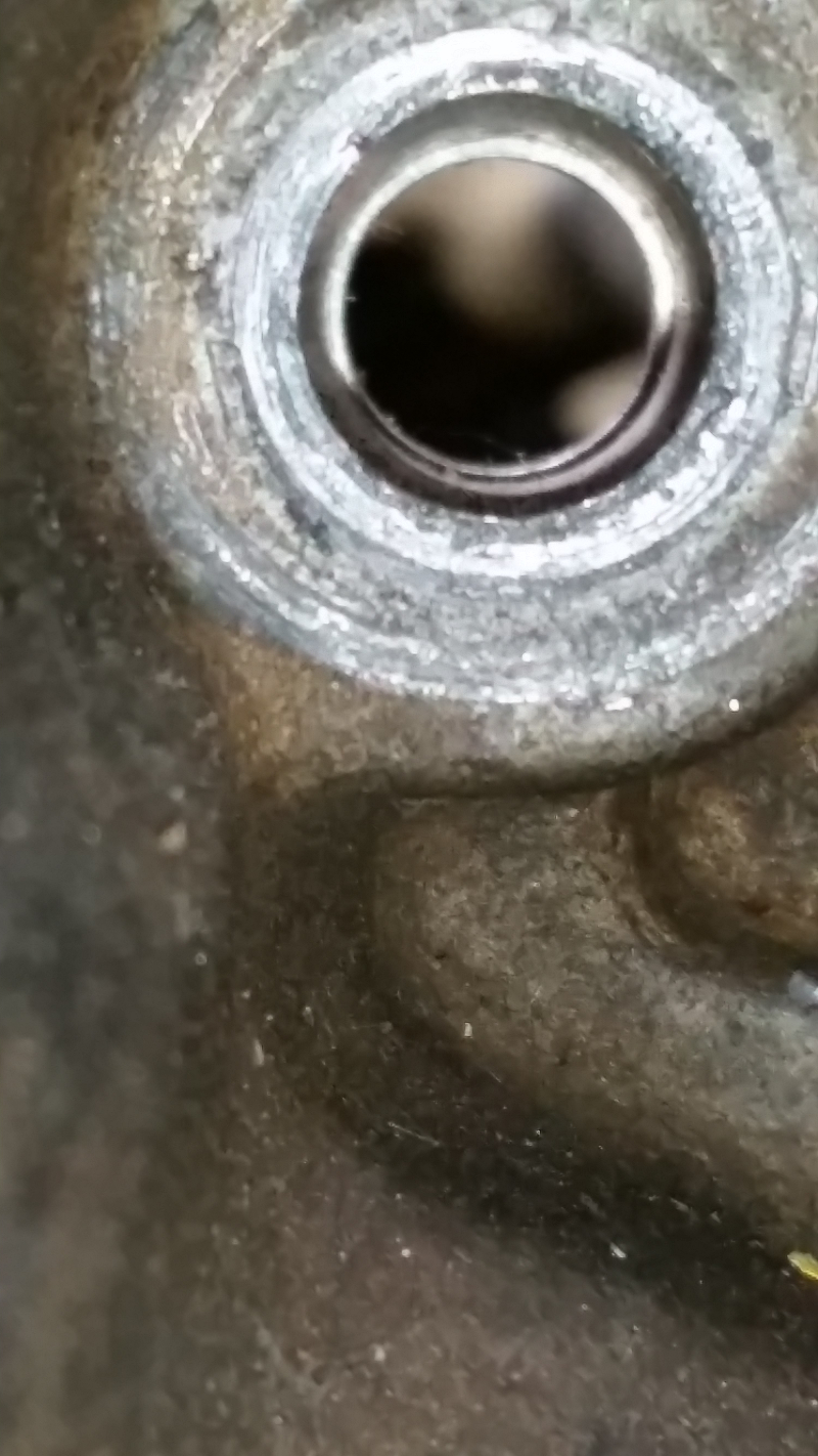
This adapter has consumed a lot of time in order to get it correct the first time. I felt the dimensions for the Cummins side of the adapter were pretty solid, but the dimensions for the Windsor block side of the adapter came mostly from the internet and we all know how reliable the internet is. Particularly, one dimension for the transmission bolt hole was different depending on the source. I needed to verify hole positions as best as possible before proceeding. I created a sheet metal part that contained all the holes from both sides of the adapter plus a pilot hole to align the input shaft to and had it cut out at work.
I fit it to both ZF5s and the R2.8 and confirmed holes at least looked correct. Several holes have spacing that needs to be accurate to within a thousandth of an inch or so, which is hard to verify accurately. The other holes could be +/- 0.10".
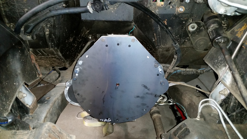

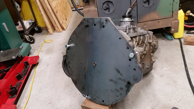
The mounting hole in question looks well centered based on the dimension I assumed was correct, but there is enough slop in this hole it likely doesn't matter.
Re: Digger's '69 Build Thread
Posted: Sun Mar 31, 2019 2:03 pm
by Digger
Re: Digger's '69 Build Thread
Posted: Sun Mar 31, 2019 2:13 pm
by Digger
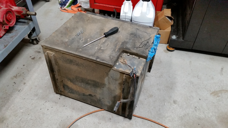
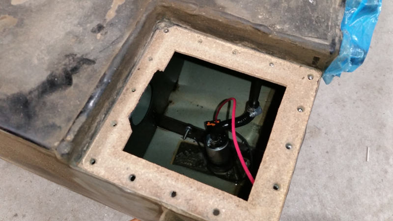
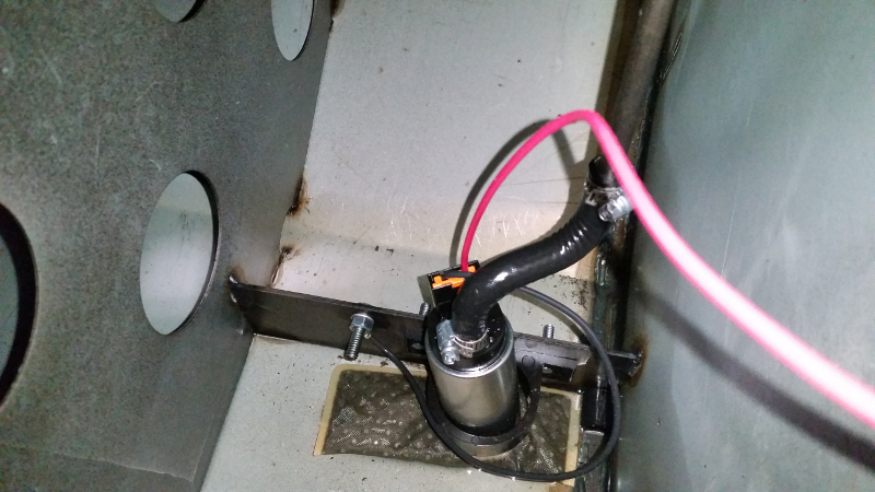
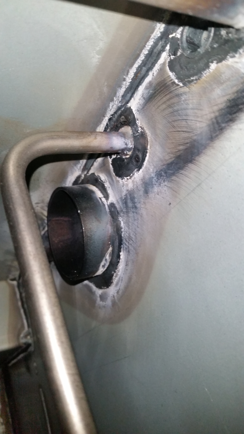
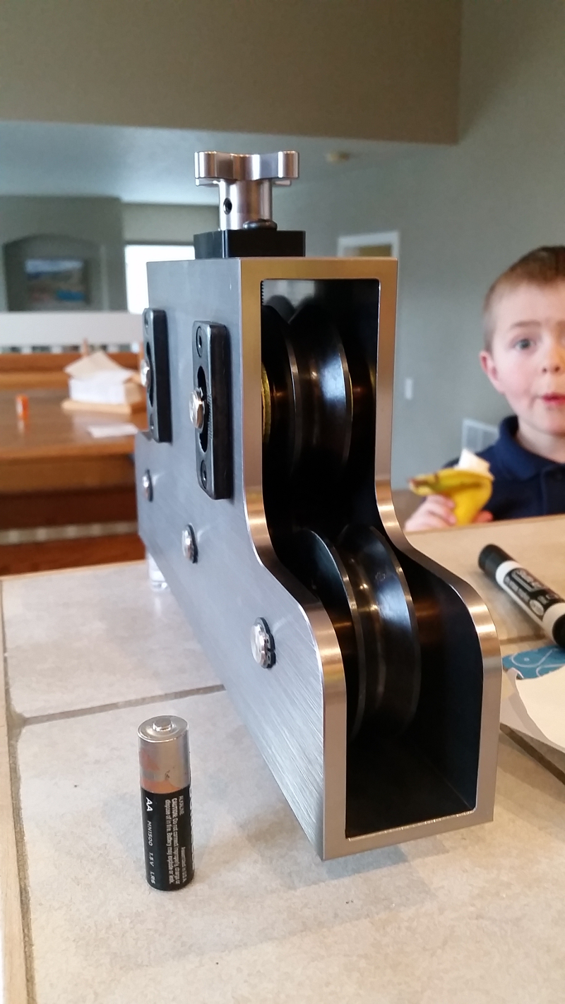
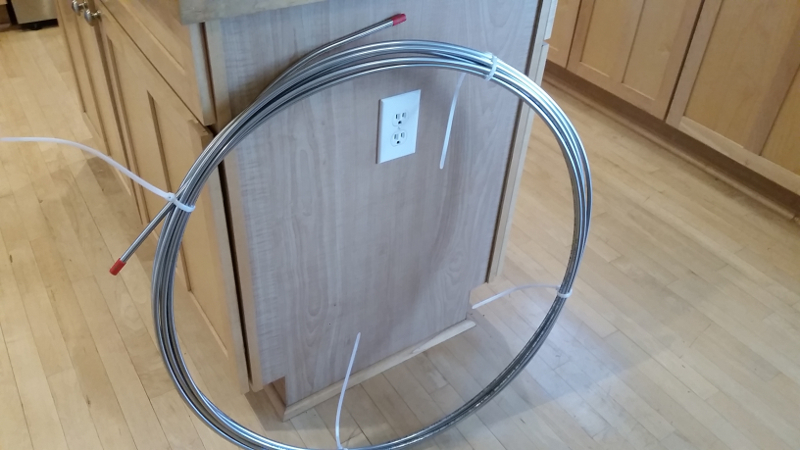
Since the fuel system is getting rearranged, I will have to run new hard lines. Wanting to do things a little nicer than last time, I'm upgrading to stainless for brakes and fuel. I decided to order a roll of tubing instead of straight pieces to eliminate any fittings along the frame rail.
This tube straightener is much bigger than I thought.
The roll of 3/8" tube is HUGE
After some additional CAD modelling, it became clear the stock engine mounts will not work. They are too far rearward in the engine bay. I could get the engine mounted but the stock mounts prevent the Cummins starter from being removed without pulling the engine. So those have to go.
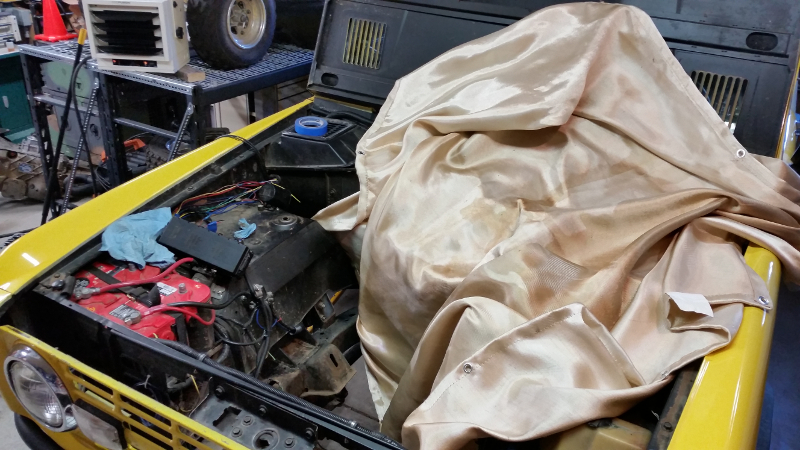
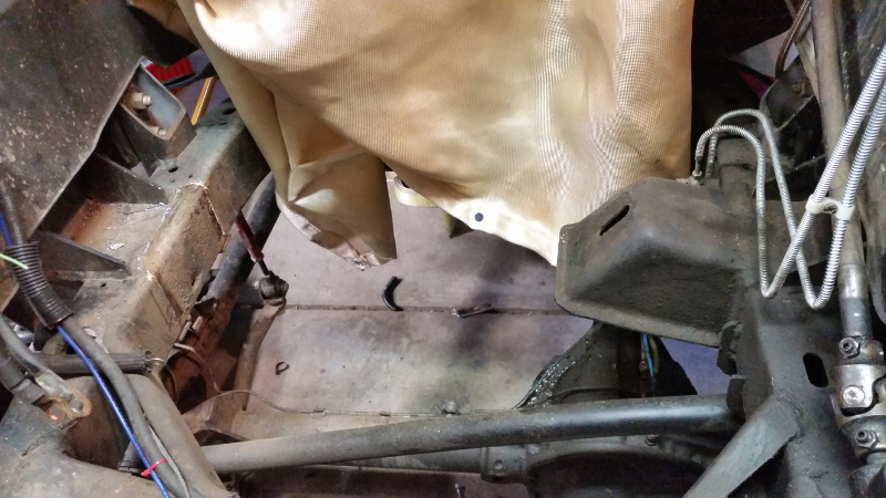
Annnnnd gone.
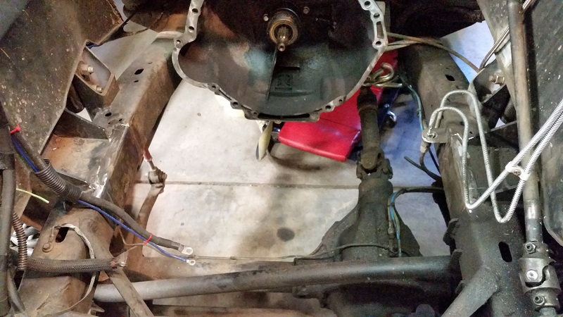
Re: Digger's '69 Build Thread
Posted: Sun Mar 31, 2019 2:23 pm
by Digger
Getting back to the adapter...
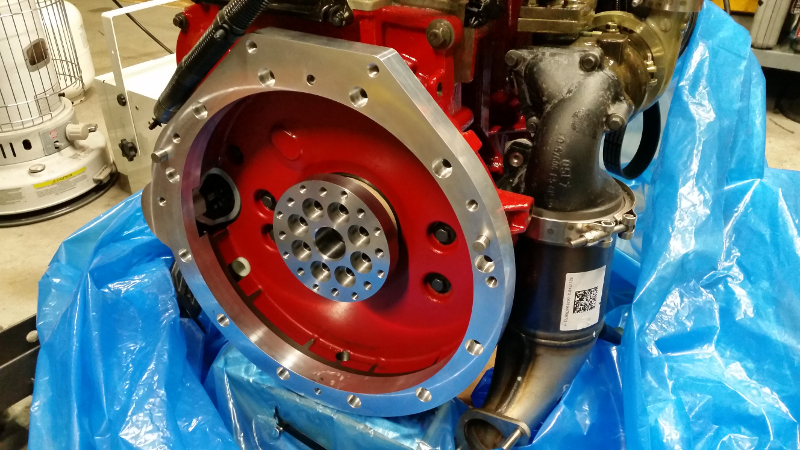
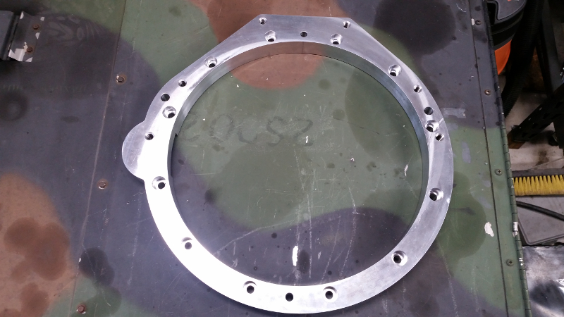
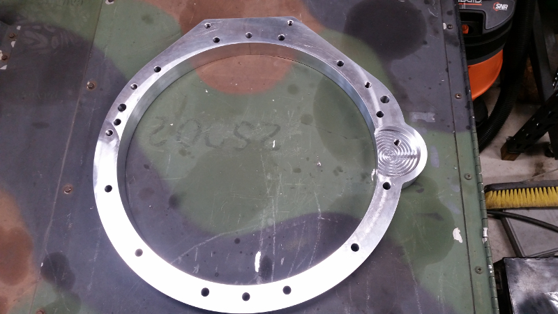
I spoke with our manufacturing engineer at work in order to get a recommendation on a machine shop. (our shop is busy most of the time) He looked at my project and thought we could fit it into the schedule, so we had some back and forth discussing how to produce my bell housing adapter, what machine should run it, who would program it and what was critical. I went ahead and purchased the raw material, a 50lb slab of 6061-T651 aluminum plate that measured 18"x18"x1.5"
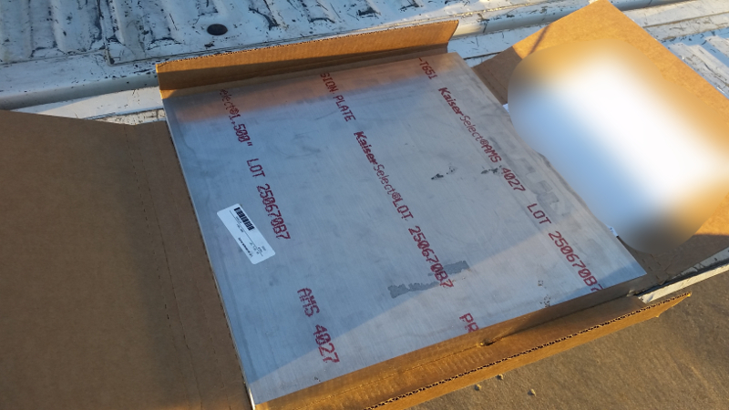
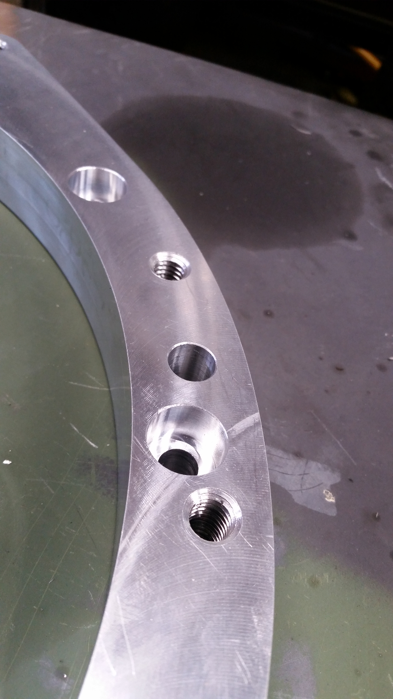
After about 4 weeks, it was time to run my part. The guys really did a great job. It was run in a horizontal mill with a pallet changer and a 35HP spindle. It made short work of my plate.
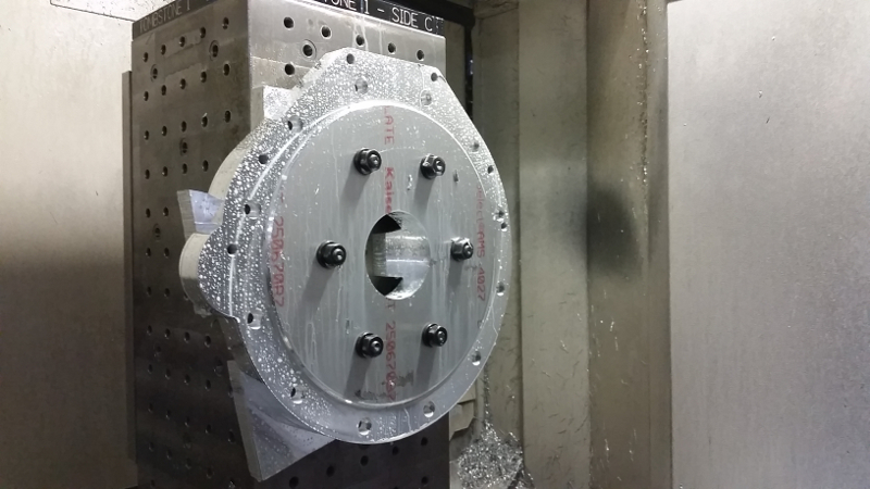
The final product is beautiful and dead accurate. The guys CMMd the part and the critical dowel pins holes were all within 0.0002" of their nominal positions. The dowel holes were reamed, so press fit will be very precise.
Re: Digger's '69 Build Thread
Posted: Sun Mar 31, 2019 2:39 pm
by Digger
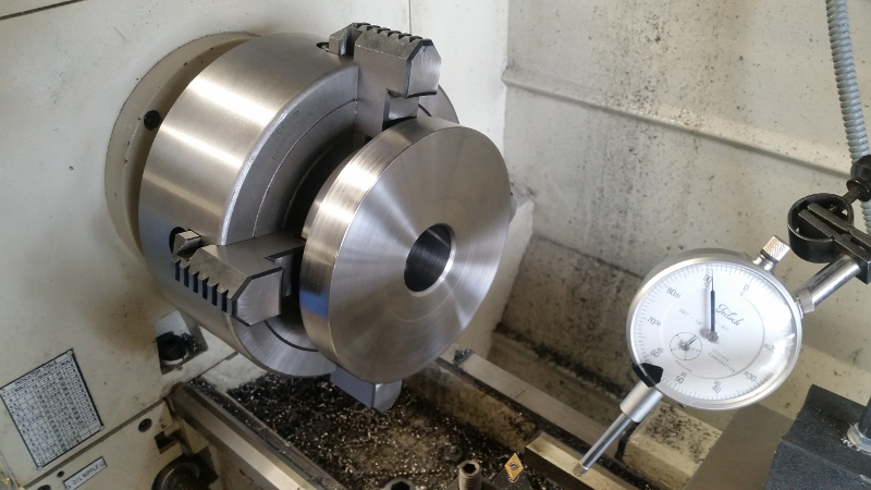
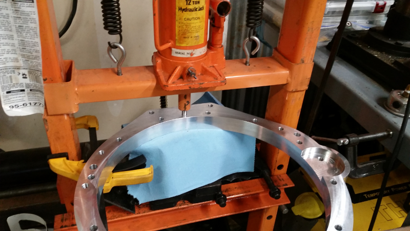
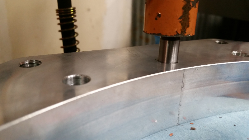
With the bellhousing adapter finished, I needed turn the 10mm dowel pins down slightly. Given that the holes in the engine were reamed, I didn't have the right measuring tool to accurately measure the ID to 0.0001". So I ordered standard +tolerance dowel pins and test fit them. They almost wanted to go, but not quite. Because the dowels locate the engine to adapter to transmission, I couldn't just chuck them in the 3-jaw and turn them with cutting tools. I needed something more precise. Generally when you're working under 0.001", you need to grind, not cut, so I rigged up a makeshift tool post grinder with a Dremel tool. I also loaded the 4-jaw chuck and dialed the dowel pin to the lathe so there was less than 0.0001" runout.
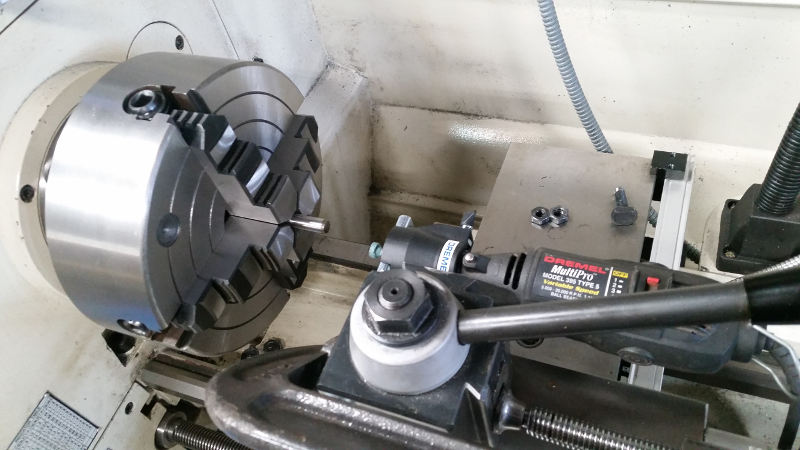
I ended up taking off 0.0004" over 4 passes of the grinder.
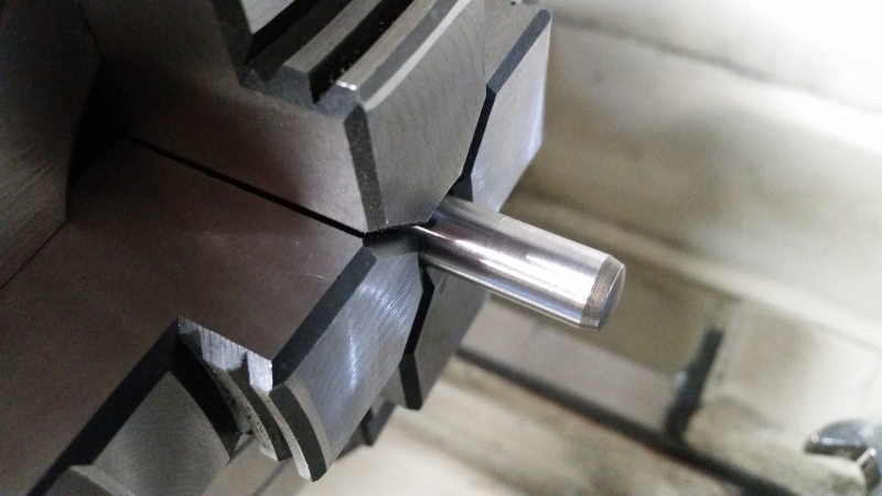
You can barely tell anything was done, but the upper 14mm of the dowel is a smaller OD.
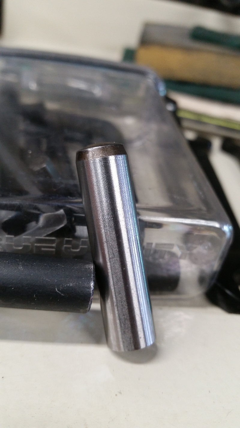
Now the pins slides in easy, but is still tight enough to seal the air behind it.
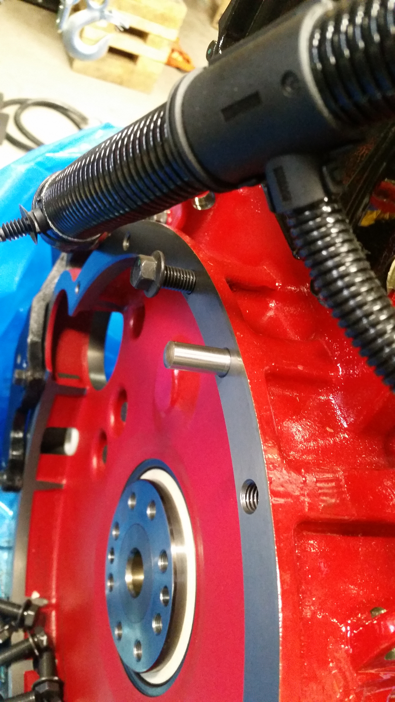
After grinding a lead-in chamfer, I pressed all 4 dowels into place.
Re: Digger's '69 Build Thread
Posted: Sun Mar 31, 2019 2:45 pm
by Digger
Now for the moment of truth...
.
.
.
.
.
.
.
.
.
.
.
.
.
.
.
.
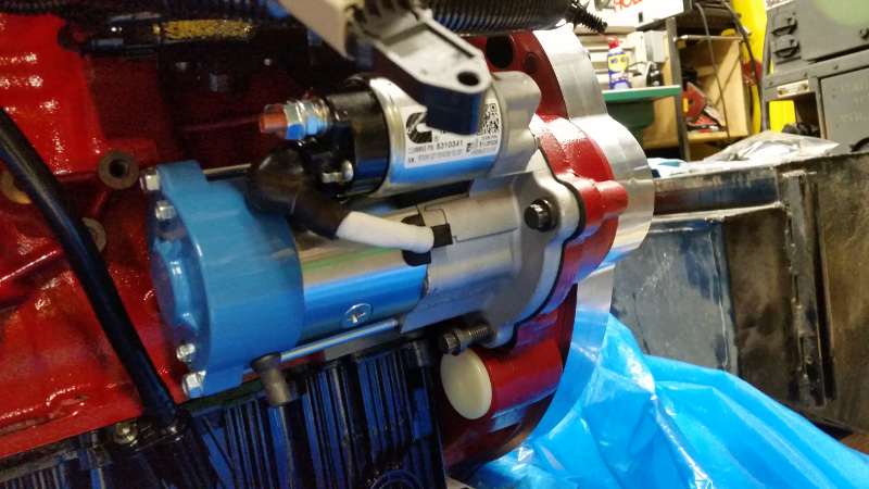
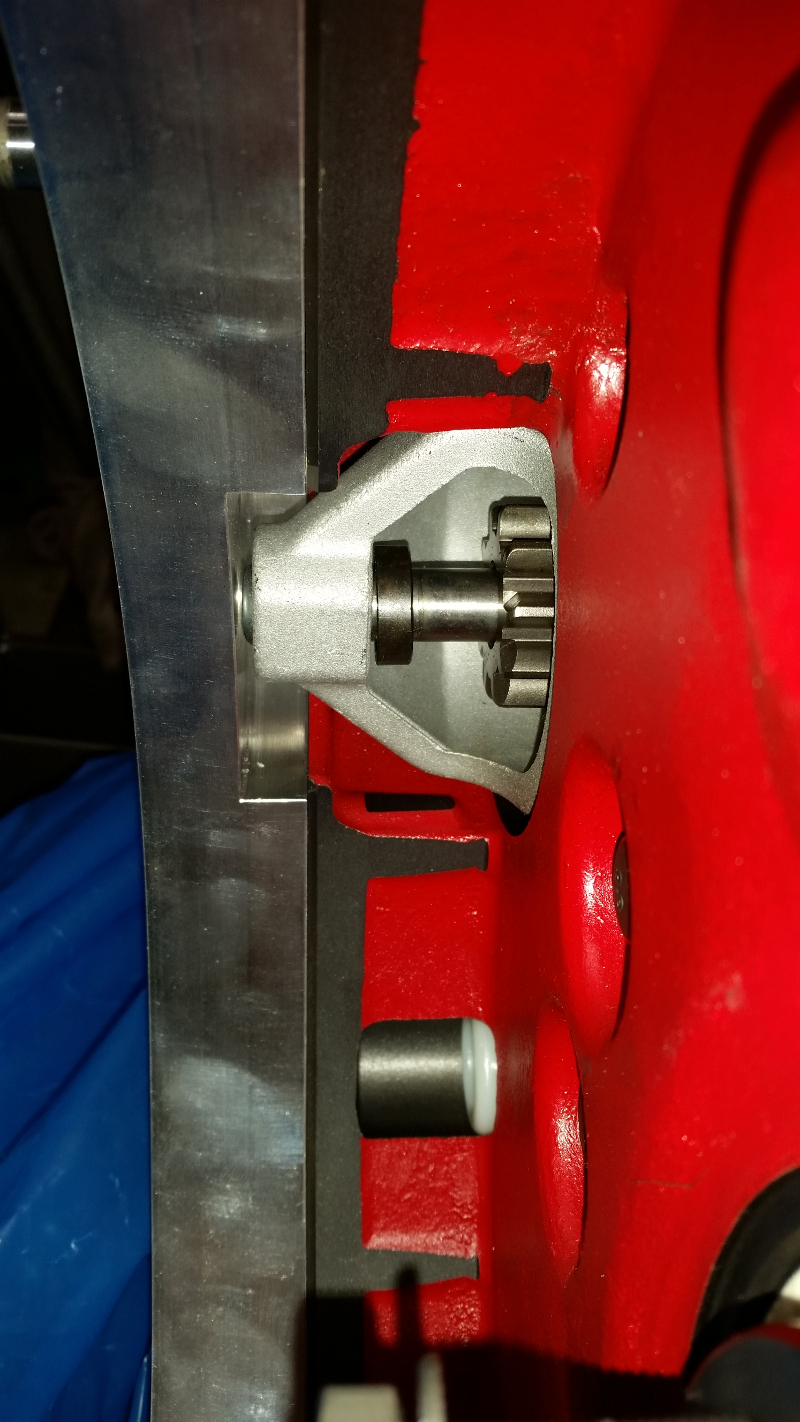
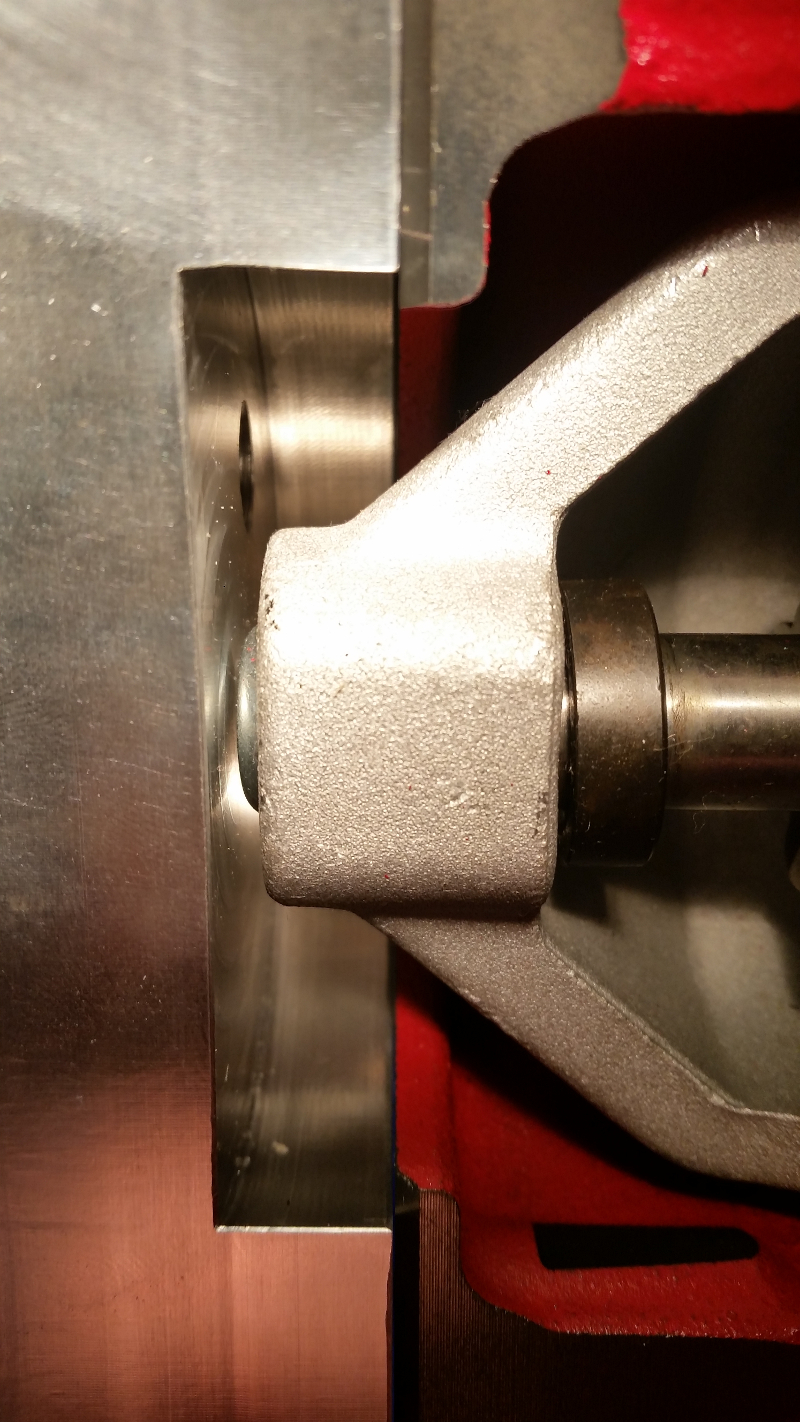
Perfect!
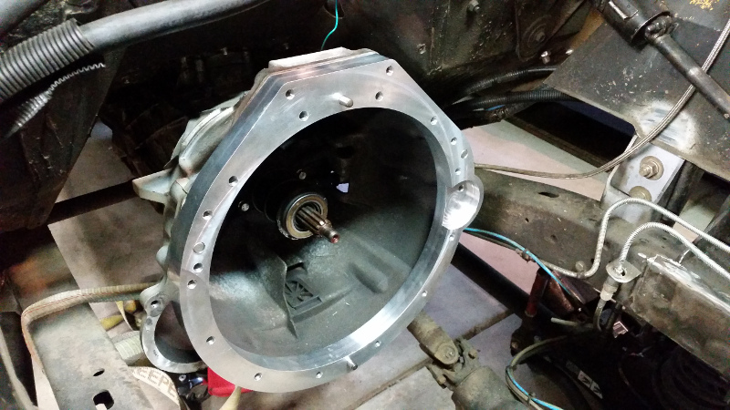
The fit on the engine side was so perfect and tight, I had to slide the adapter in very squarely or it could get stuck, but lined up right, it just slid right on.
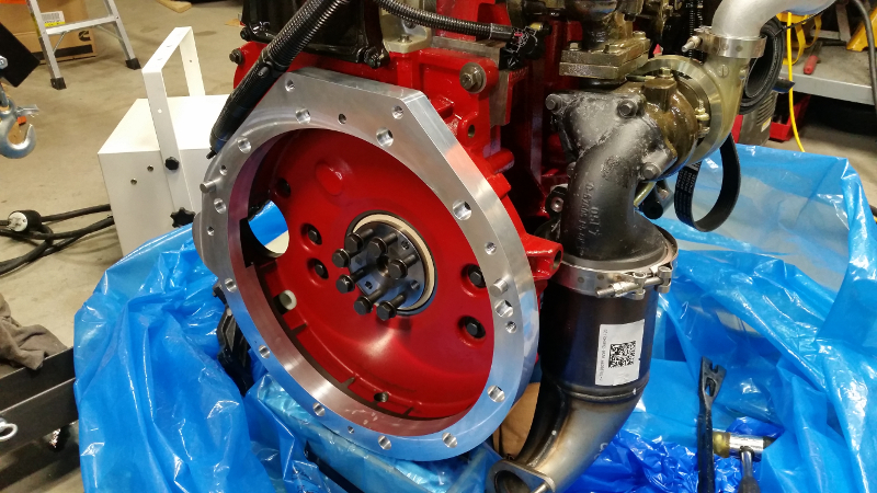
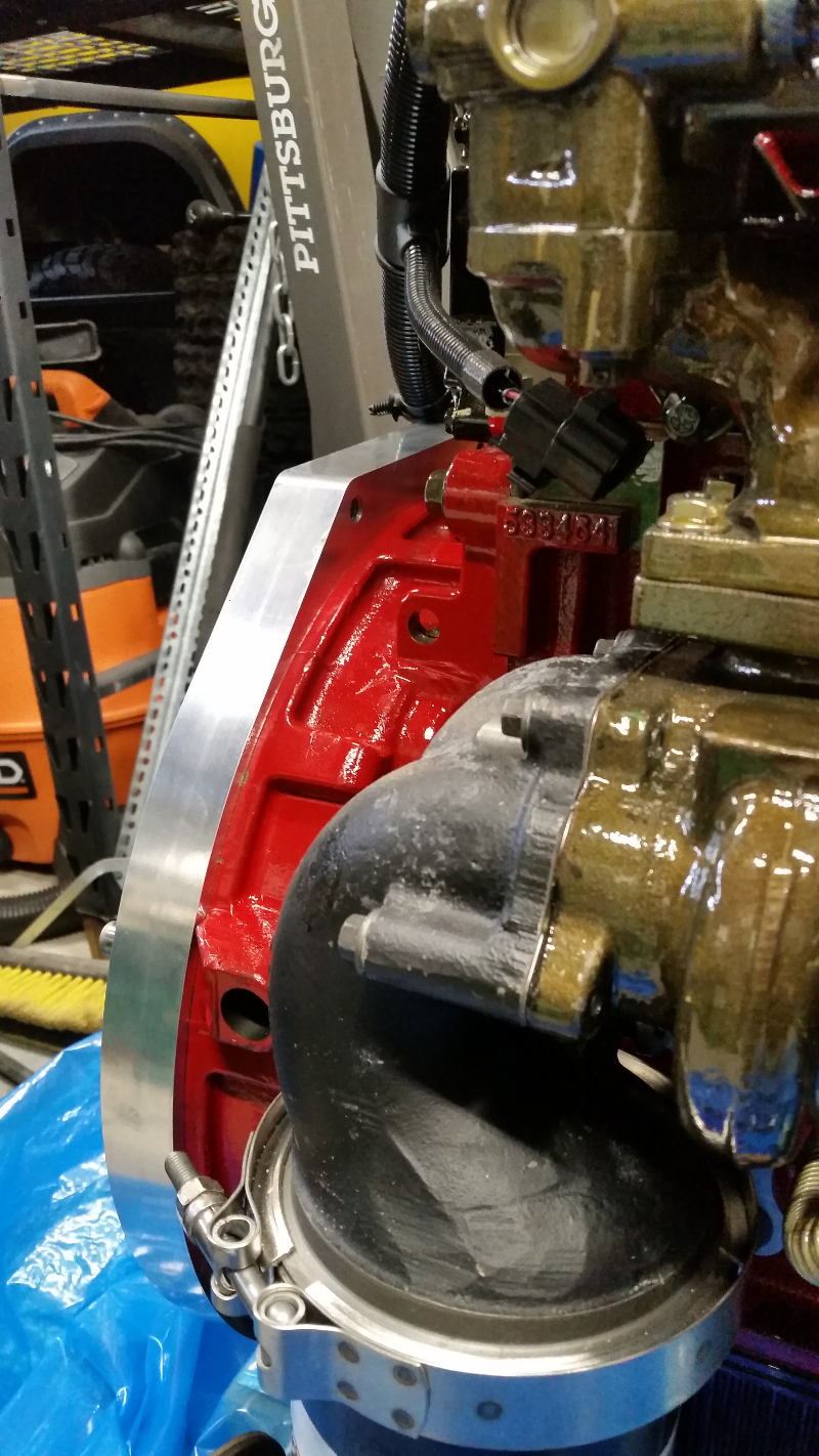
I also checked the starter clearance. Just enough.
Re: Digger's '69 Build Thread
Posted: Sun Mar 31, 2019 2:58 pm
by Digger
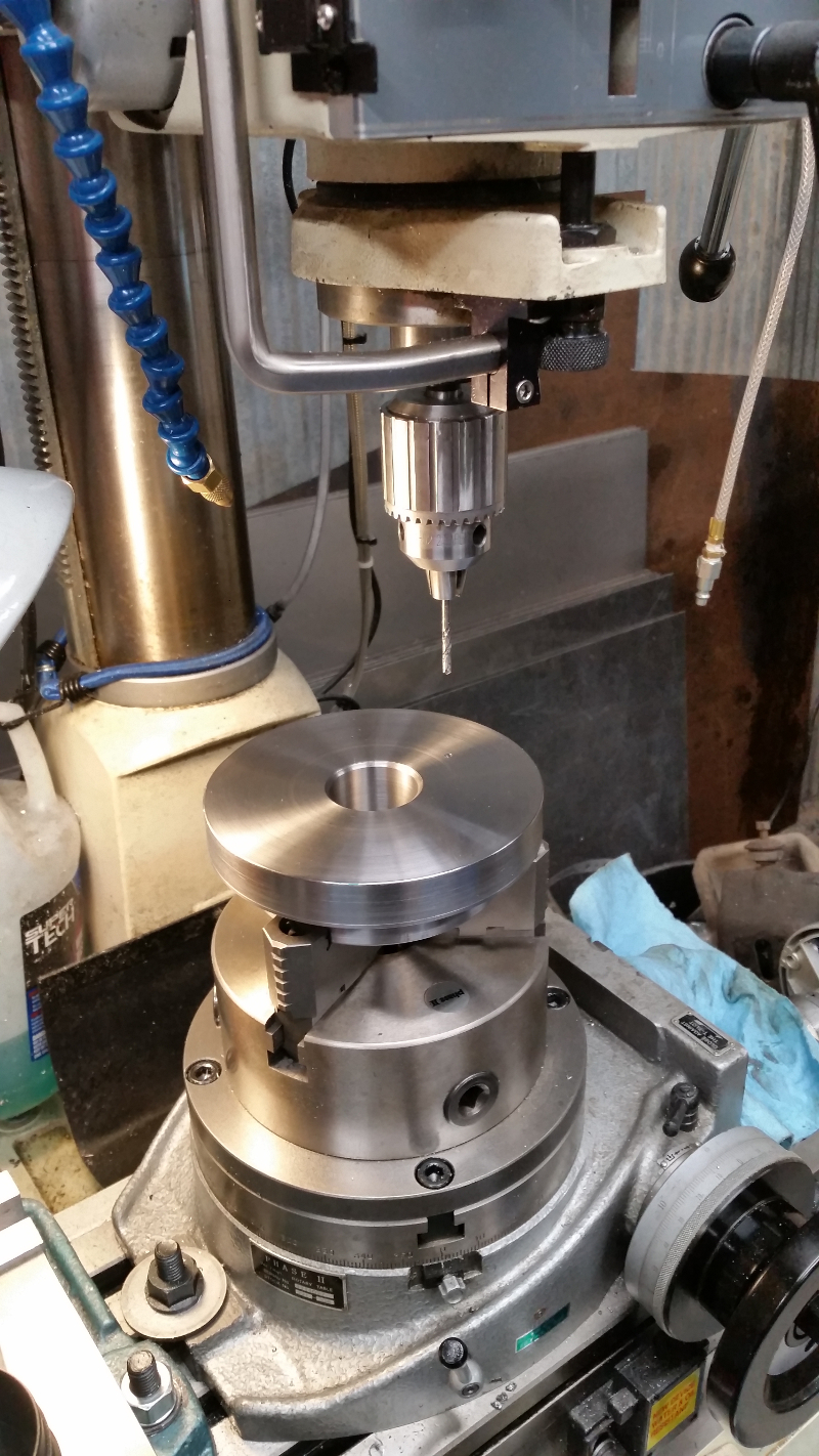
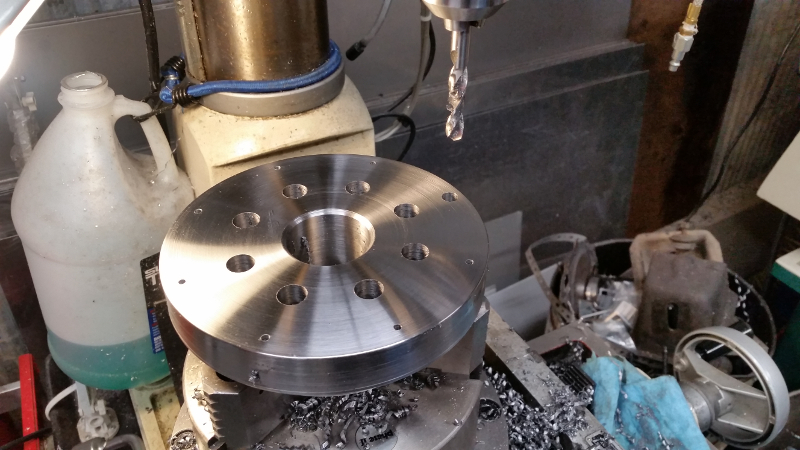
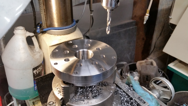
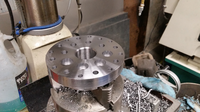
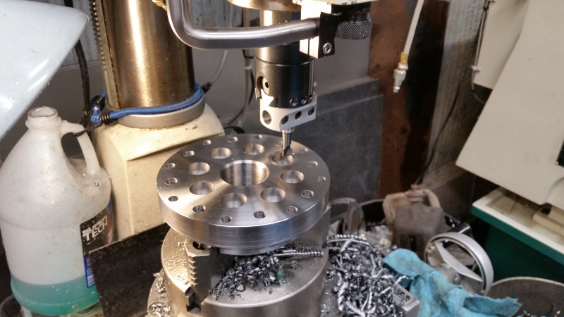
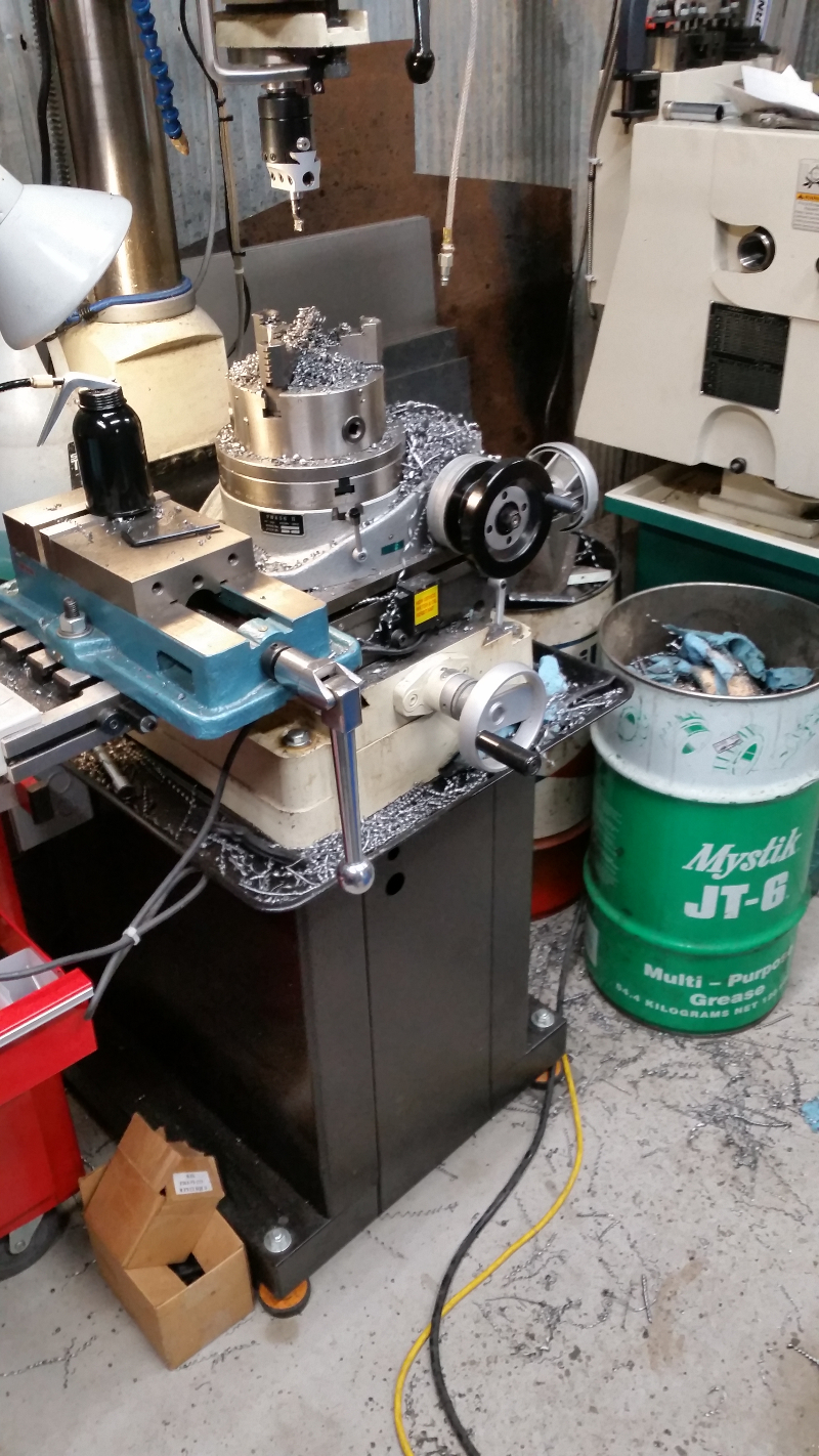
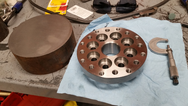
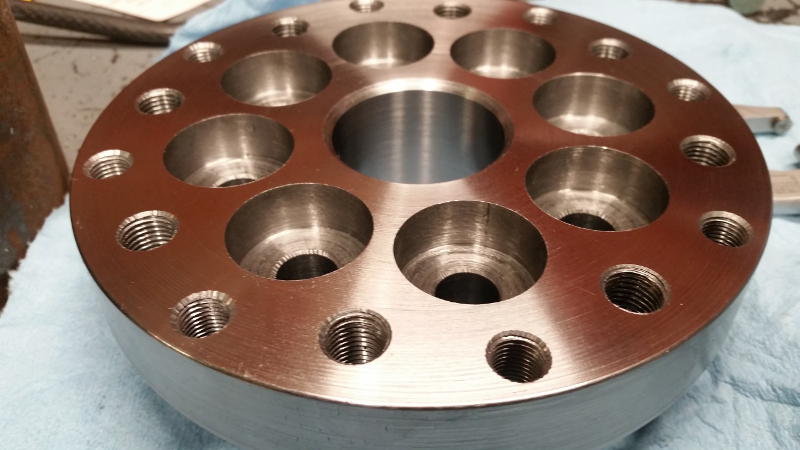
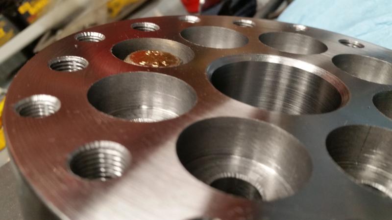
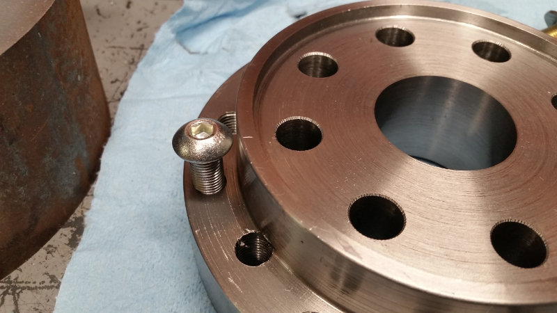
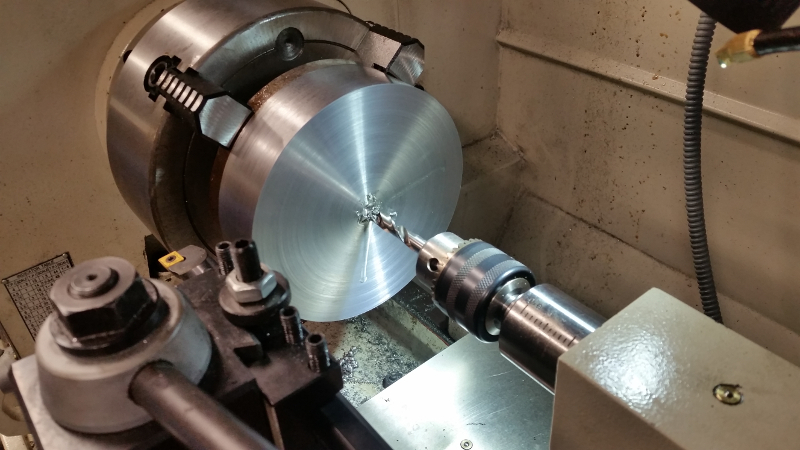
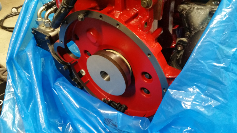
While the guys at work were machining the bellhousing adapter, I was at home working on the crank adapter. I already had to redesign this once after sourcing material proved to be difficult. Now it's a little smaller. The crank adapter proved to be a challenge to manage all the tolerance stackup over all the features of two adapters plus flywheel etc. After giving some thought to the manufacturing approach, I got started.
Starting out with raw stock...
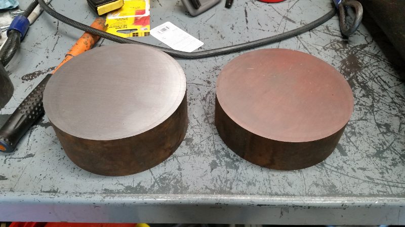
...I faced the part (after dialing it into the lathe), punched the center bore which located the 2nd crank adapter, and turned the counterbore that locates the adapter to the crank. Tolerances for the critical features were all sub-thousandth of an inch. I was aiming for 0.0003 or less deviation from print.
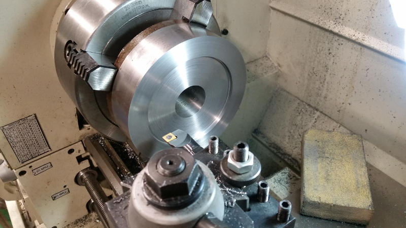
Turning the hub face for the starter ring
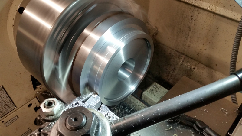
A-side completed.
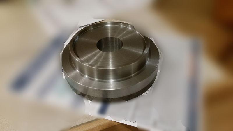
And test fitted
Re: Digger's '69 Build Thread
Posted: Sun Mar 31, 2019 3:09 pm
by Digger
Re: Digger's '69 Build Thread
Posted: Mon Apr 01, 2019 4:19 am
by Kinder
Just Wow!
Re: Digger's '69 Build Thread
Posted: Mon Apr 01, 2019 8:09 am
by Jesus_man
Kinder wrote:Just Wow!
Amen!!
Man that is some sexy stuff right there!!! What an awesome process! I would love to be your apprentice through all this!
Re: Digger's '69 Build Thread
Posted: Mon Apr 01, 2019 9:06 am
by mickphatmac
Kinder wrote:Just Wow!
No.... Sh*!!!!

Re: Digger's '69 Build Thread
Posted: Mon Apr 01, 2019 10:15 am
by landshark
you have gone

. love it
Re: Digger's '69 Build Thread
Posted: Mon Apr 01, 2019 6:26 pm
by pgilbeau
Great work, you make it look easy!
Re: Digger's '69 Build Thread
Posted: Mon Apr 01, 2019 8:17 pm
by BroncoRaider

Unbelievable.
Re: Digger's '69 Build Thread
Posted: Tue Apr 02, 2019 2:55 am
by BOBS 2 68S
Very nice!
Machinist porn on the Bronco porn site
Re: Digger's '69 Build Thread
Posted: Tue Apr 02, 2019 7:45 am
by Eck