Page 12 of 17
Re: Digger's '69 Build Thread
Posted: Wed Apr 03, 2019 12:15 pm
by Strike2
Those are parts are beautiful!
BUT
Re: Digger's '69 Build Thread
Posted: Wed Apr 03, 2019 1:32 pm
by phyler
Strike2 wrote:Those are parts are beautiful!
BUT
Seriously.
Sent from my Pixel 2 using Tapatalk
Re: Digger's '69 Build Thread
Posted: Wed Apr 03, 2019 2:41 pm
by TOOLMAN
Strike2 wrote:Those are parts are beautiful!
BUT
Indeed!
Re: Digger's '69 Build Thread
Posted: Wed Apr 03, 2019 7:22 pm
by Digger
Strike2 wrote:Those are parts are beautiful!
BUT
lol, you guys are hilarious.
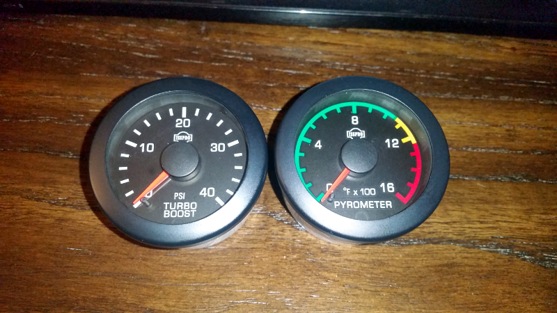
Not much of an update tonight. My boost and pyro gauges showed up. I like clean look and color coding on the pyro.
Re: Digger's '69 Build Thread
Posted: Thu Apr 04, 2019 5:10 am
by ZOSO
We better see that boost gauge pegged once.
Re: Digger's '69 Build Thread
Posted: Thu Apr 04, 2019 6:45 am
by Kinder
Digger wrote:Strike2 wrote:Those are parts are beautiful!
BUT
lol, you guys are hilarious.
Not much of an update tonight. My boost and pyro gauges showed up. I like clean look and color coding on the pyro.
IΓÇÖm interested to see what your boost & EGTs are once you get it running. Comparing normal around town driving conditions and then when youΓÇÖre asking it for everything it has.
Re: Digger's '69 Build Thread
Posted: Thu Apr 04, 2019 8:03 am
by Digger
Kinder wrote:Digger wrote:Strike2 wrote:Those are parts are beautiful!
BUT
lol, you guys are hilarious.
Not much of an update tonight. My boost and pyro gauges showed up. I like clean look and color coding on the pyro.
IΓÇÖm interested to see what your boost & EGTs are once you get it running. Comparing normal around town driving conditions and then when youΓÇÖre asking it for everything it has.
Me too. As I understand it, the 2.8 makes about 28psi max.
EGTs are an unknown and a big reason why I bought a gauge. Towing in the mountains as you know really works an engine.
Re: Digger's '69 Build Thread
Posted: Thu May 09, 2019 9:44 pm
by Digger
Making a little more progress.
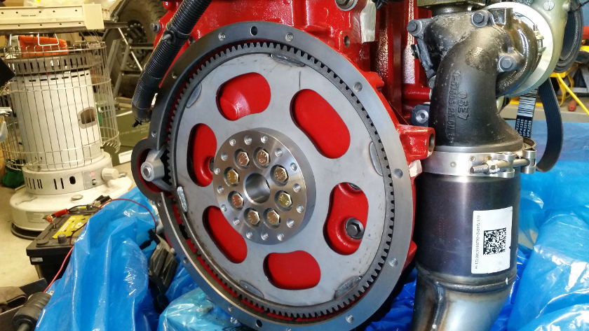
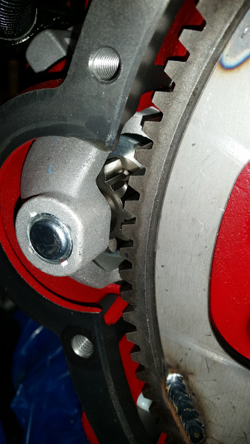
I had a flex plate laser cut for the starter gear. I measured some runout due to heat warpage. I used a dial indicator and a crescent wrench to straighten it out.
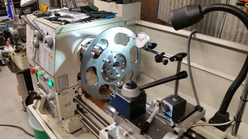
With the gear fitted up and restraighten, I covered the lathe and tack welded the gear in place, then pulled it and fully welded it.
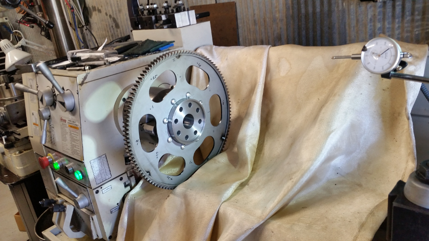
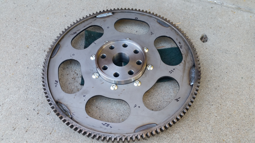
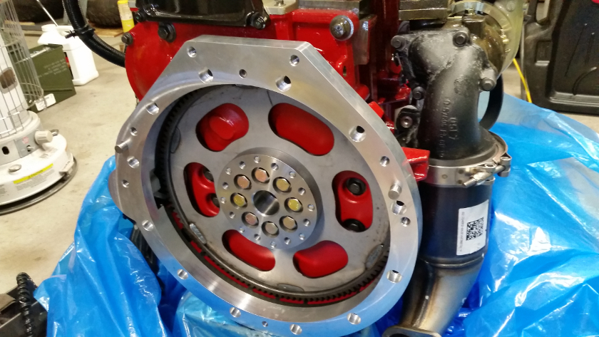
Test fitted
Re: Digger's '69 Build Thread
Posted: Thu May 09, 2019 9:52 pm
by Digger
On to the 2nd crank adapter.
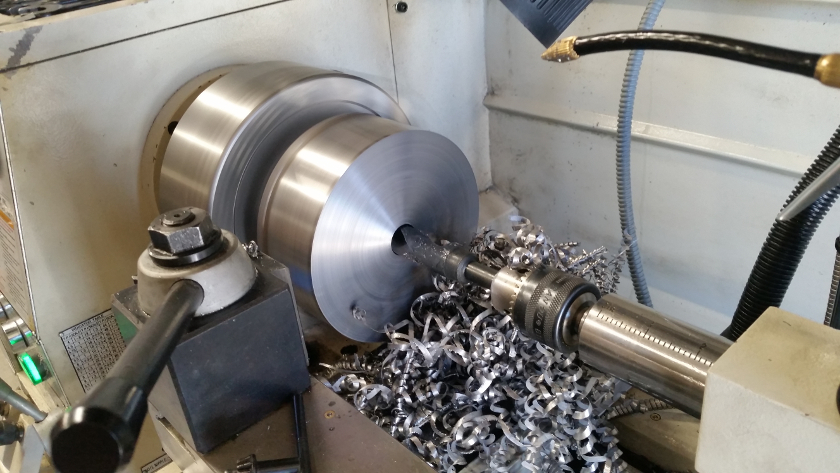
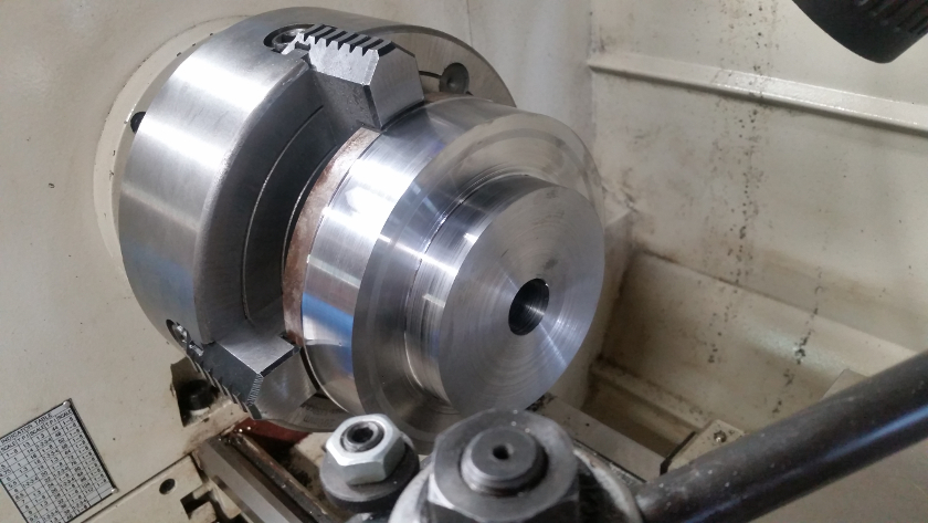

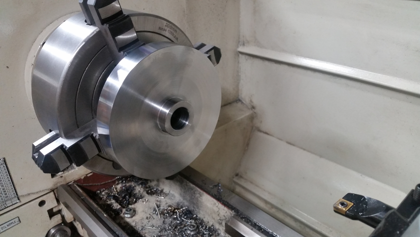
Test fitting with the mating part to ensure exact fitment and verify pilot dimensions.
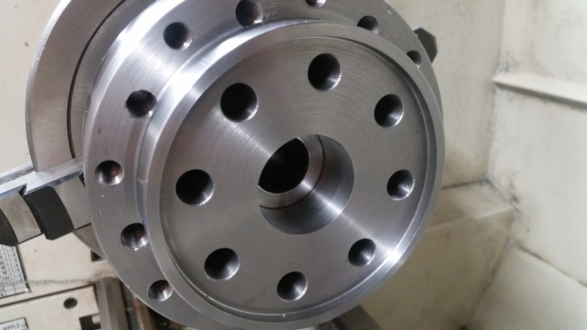
Afterwards, I tested combined runout. It wasn't too bad, .0001" - .0004" depending on which surface was measured.
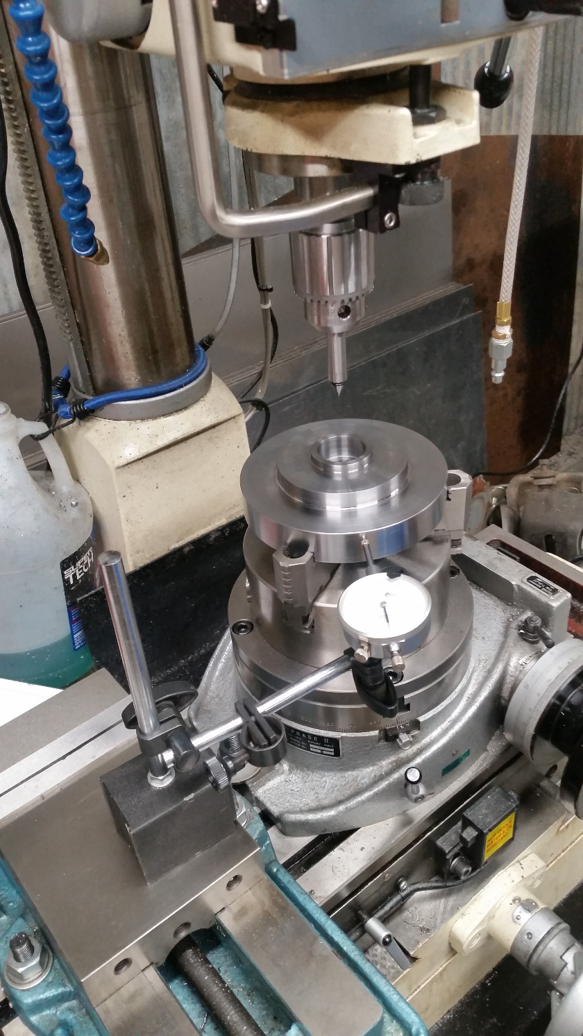
Before drilling holes, I needed to line up the spindle to the rotary table
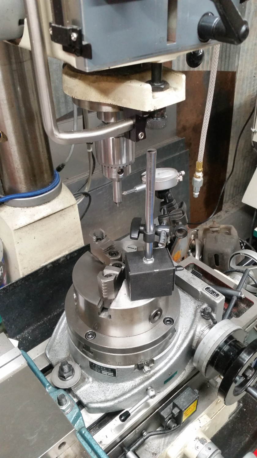
And check runout on the rotary table
Re: Digger's '69 Build Thread
Posted: Thu May 09, 2019 10:05 pm
by Digger
Center drilling the crank holes before drilling. The Ford crank pattern has one hole offset, so I needed to make sure they were all in the right locations
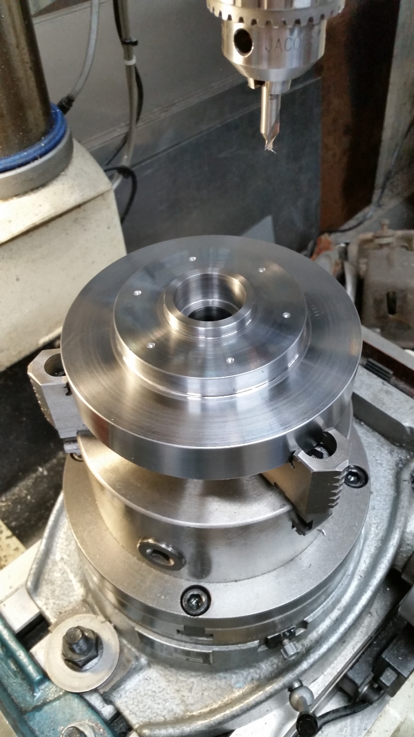
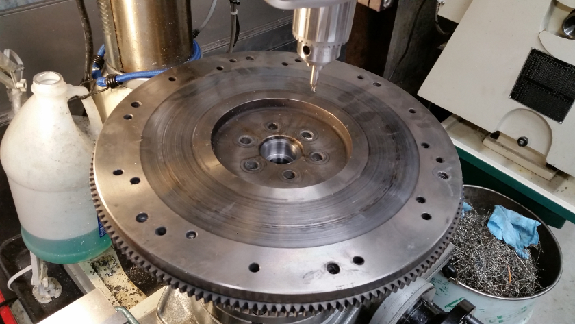
Looks good
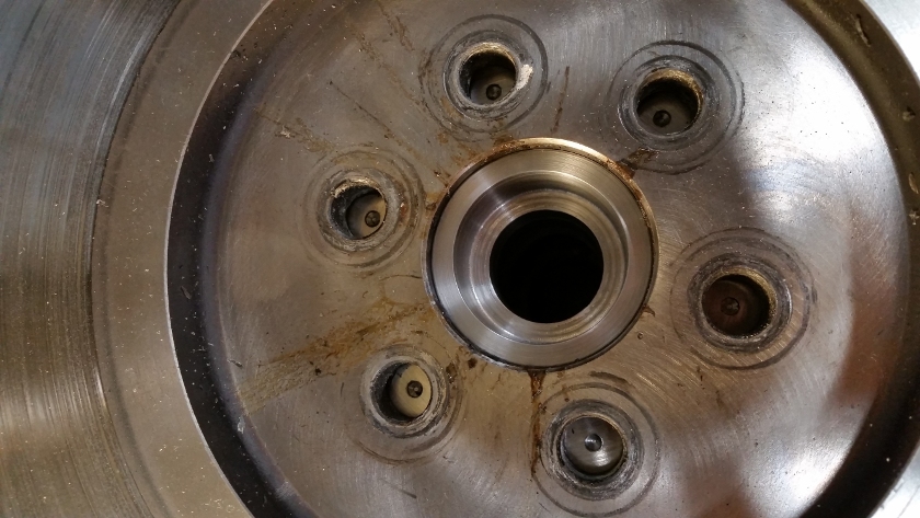
Finished up
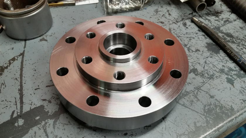
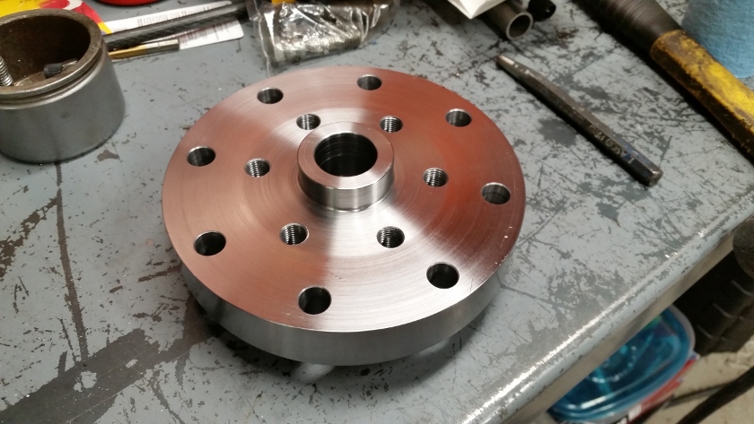
And one final fitup.
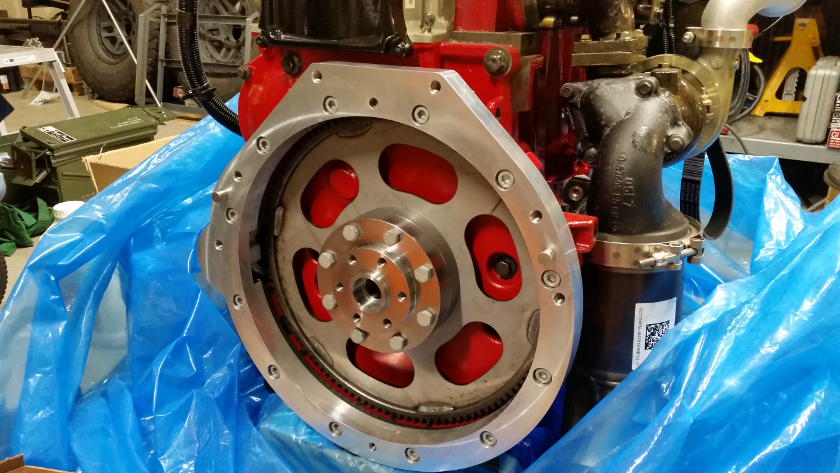

I'm pretty excited to see this finally come together. Even with the tolerance stack up of 5 different interfaces, the flywheel to bellhousing mount face was within .003" of the CAD model.
Re: Digger's '69 Build Thread
Posted: Thu May 09, 2019 11:11 pm
by Eck

Sent from my iPhone using Tapatalk
Re: Digger's '69 Build Thread
Posted: Fri May 10, 2019 3:00 am
by BOBS 2 68S
What Eck said
Re: Digger's '69 Build Thread
Posted: Fri May 10, 2019 4:24 am
by Kinder
Amazing, love seeing all the adapters in place, that means itΓÇÖs time to get that thing in the engine bay!
Re: Digger's '69 Build Thread
Posted: Fri May 10, 2019 6:21 am
by cpldavis37
So Cool!
Re: Digger's '69 Build Thread
Posted: Fri May 10, 2019 11:23 pm
by EBsaver
Jesse,
IΓÇÖve been following your progress...very exciting stuff here.
I cannot wait to see this thing driving w/ the turbo diesel

Nice craftsmanship!!
Hank
Re: Digger's '69 Build Thread
Posted: Sat May 11, 2019 7:29 am
by Justin
Wow. Blown away.
Re: Digger's '69 Build Thread
Posted: Thu May 23, 2019 4:28 pm
by Booger
What all these guys said. That is a trick setup to be sure. Hope to see it running in the near future.
Re: Digger's '69 Build Thread
Posted: Thu Aug 29, 2019 8:33 am
by Jesus_man
No update in 3 months?? I assume that is because you've been cruising this thing burning diesel??
Re: Digger's '69 Build Thread
Posted: Wed Sep 04, 2019 11:43 am
by cw72
Just got done spending a week with 3 R2.8 rigs, really cool motor throwing down impressive mileage on 38s.
Sent from my iPhone using Tapatalk
Re: Digger's '69 Build Thread
Posted: Wed Sep 04, 2019 6:23 pm
by Rox Crusher
I missed these recent updates.......impressive doesnΓÇÖt even begin to cover it !
Nice work
Re: Digger's '69 Build Thread
Posted: Wed Oct 16, 2019 10:40 pm
by Digger
Whew, 5 months since my last update!
Needless to say, there has been A LOT going on in my life. Too much for details. Other things needed more attention than the Bronco. Summer came and went before I knew what happened. Things are getting back to normal and the push on the Bronco has resumed.
Going back to early May, I ordered a clutch for the R2.8. Nothing special, just another McLeod like the unit I had before. I could have re-used the old one, but it was grooved and I wanted fresh parts. Well that started another fiasco similar to the intake manifold problem I had last summer that started this whole engine swap. I was getting a pit in my stomach at the prospect of waiting months for back ordered parts. I was able to track down a different clutch kit and order it. Well it showed up and it was definitely not designed for a hydraulic throw out bearing. So I jumped brands and bought a Luk clutch kit that seems like it will fit the build. Nothing fancy, just a standard clutch with a little extra holding power.
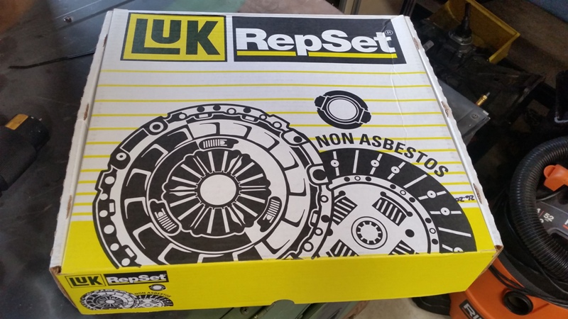
Laying all three clutches side-by-side, you could see the difference in the spring fingers. The new McLeod clutch fingers did not extend as far towards the crank centerline and the hydraulic throwout bearing wanted to pass right through. Additionally, the distance from pressure plate to top of clutch fingers was slightly different.
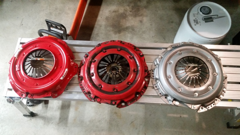
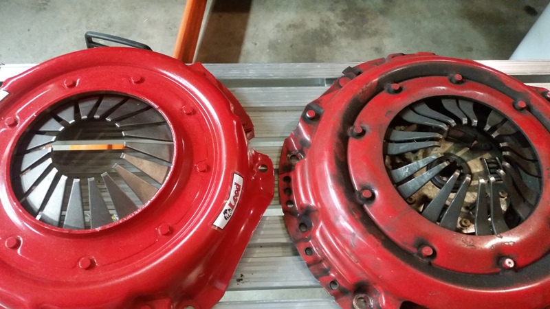
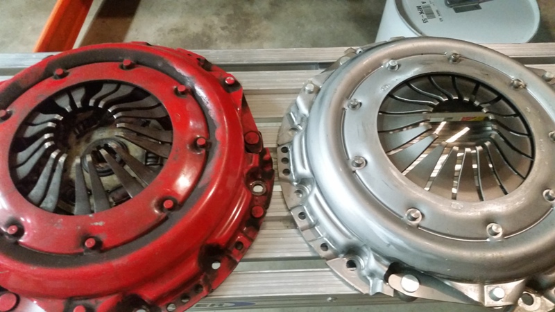
Ironically, all three pressure plates were stamped "Luk".
With new clutch in hand, about mid-June, I dis-assembled the adapter set and fit the clutch.
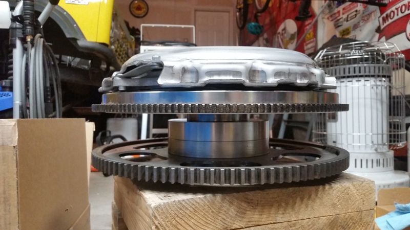
The stack of parts is pretty tall, not ideal, but it should work fine. Weight-wise, its heavy. Both the stock Ford 351 flywheel and the Cummins flywheel hover around 25lbs. The stack with adapters is pushing 45lbs. However, the majority of that weight is much closer to the crank centerline, so additional rotational inertia is minimized. Add the clutch set in the mix and I don't think the impact will be too bad. Some guys have stacked two flywheels weighing over 60lbs with adapters, so I'll be okay.
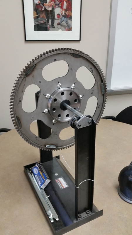
The main reason for pulling the adapter was to check balance on my flex plate. The adapters themselves don't really need a balance, as they are very true and closer to crank centerline. Maybe someday when I build my dynamic balancer, I'll throw in the whole thing on.
To check balance on the flex plate, I borrowed a motorcycle wheel balancer. Since the flexplate has a high diameter:length ratio, a static balance is good enough. A few of us at work played with it for a while, but the unit was very true and well balanced, so no weight was removed. We double checked our selves by adding weight at different points to verify the unit was truly balanced with the weight removed.
Re: Digger's '69 Build Thread
Posted: Wed Oct 16, 2019 10:57 pm
by Digger
Thanks to the CAD model Bronco, I knew going in that the Diesel Oxidation Catalyst (DOC) would not fit between the engine and frame rail. I do intend to keep it and maintain the emission equipment, but it will need to be moved downstream a bit. Originally I planned to use a different turbo exhaust elbow from another 2.8 ISF application, but after studying the CAD model, decided it would be easier to route the exhaust like the passenger side of the 351. There was no off-the-shelf turbo outlet for this, so I drew up a flange in SolidWorks and printed out the template.
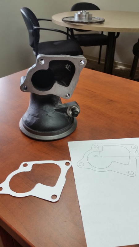
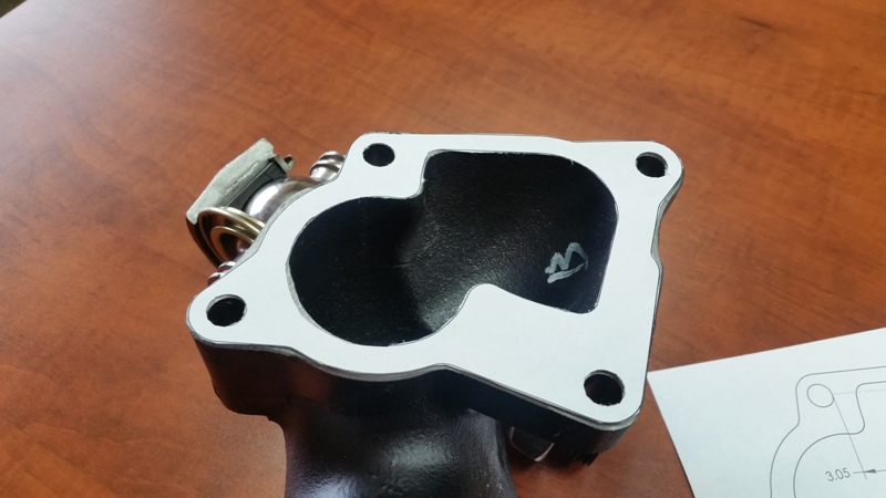
Comparing it to the old turbo outlet, it looked correct. A friend of mine cut the flange out on his waterjet. I neglected to get a picture, but it fit perfect. More on that later when I build the exhaust.
With flexplate balance confirmed, it was time for the FINAL assembly. I installed the pilot bearing. Fitment was very good.

I researched and calculated all the torque specs based on known tables and my experience at work with bolt testing. It's pretty interesting stuff if you want to "dork out" for a while. Bolt finishes have an impressive impact on torque specs. All bolts were loctite'd and torqued down, then marked.

Clutch installed:
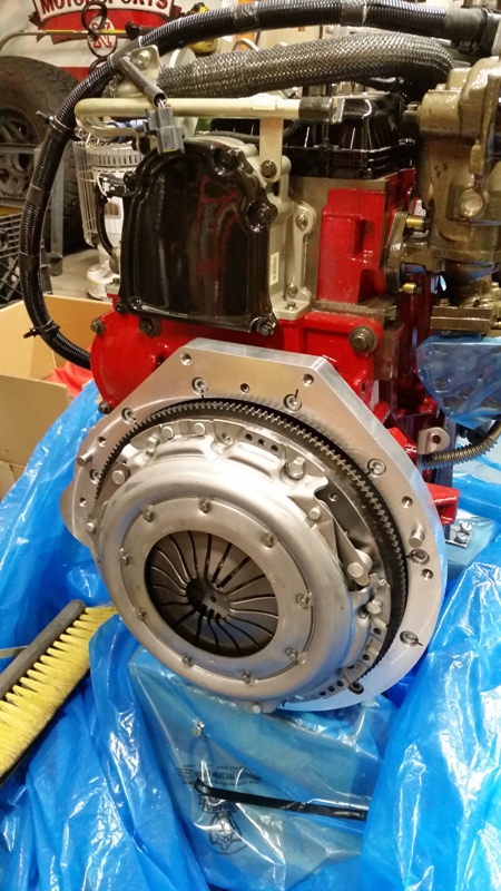
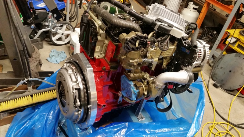
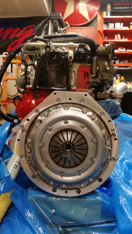
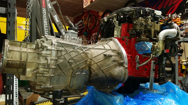
Before attempting to install the engine, I pulled my spare ZF-5 to verify the transmission will bolt up without issue. It went pretty smoothly, but the transmission would not slide all the way together with the engine adapter. Fearing the worst, I pulled the clutch and re-assembled it, taking great care to center up the friction disc. Still a No-Go. The transmission did not want to slide the last 1/8". I pulled it apart again, but removed the clutch. BOOM, transmission slide right into place. OKAY, now I know it's not the adapter or pilot bearing.
I played with the clutch some more and determined the input shaft just really fits tight on the friction plate splines. A minor amount of help from the transmission mounting bolts and the two pulled right into place.
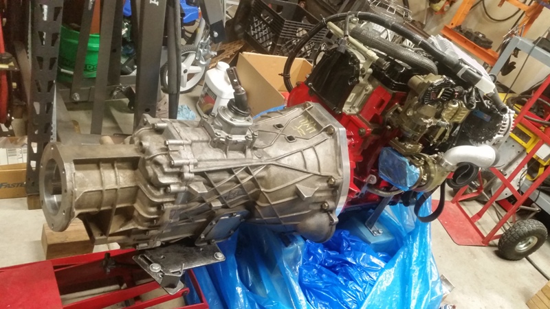
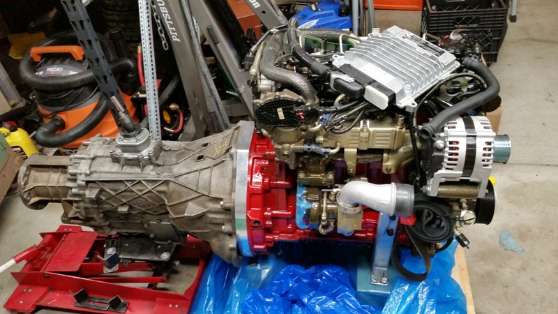
It was really exciting to see the two mated up for the first time!
Re: Digger's '69 Build Thread
Posted: Wed Oct 16, 2019 11:15 pm
by Digger
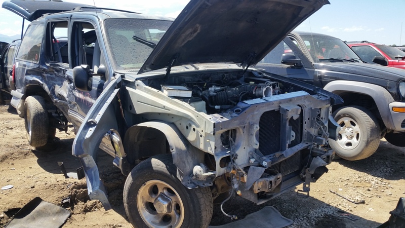
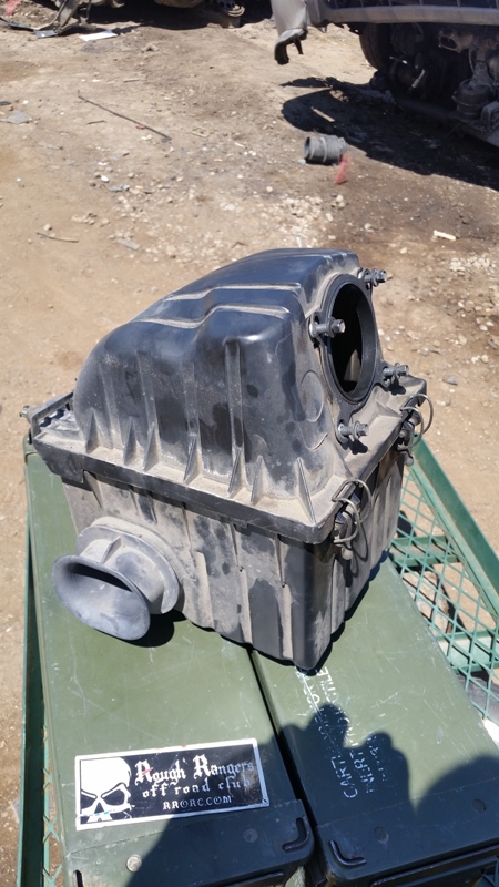
With a free Saturday, I headed over to U-Pull-n-Pay to scout for some parts. I ended up pulling the air filter box from a V8 Explorer of all applications.
I'll need to fabricate a hose to flange adapter to replace the MAF, but that will be okay.
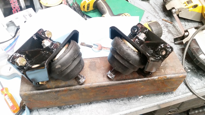
Back home, I spent a few evenings researching motor mounts. I wanted to re-use the existing frame mounts and MAYBE OEM motor isolators. But it just wasn't going to work. SO, I looked around and discovered most Cummins swap guys are using canister type isolators with threaded studs protruding from each end. It's a straight-forward way to mount the engine. My goal is to use as many OEM parts as possible to improve service-ability. The canister-type mounts have been used by many brands, but it turns out Ford used them on 300 I6's in the last 80s/early 90s. So a trip to the parts store and I bought a set.
After modeling them up in Solidworks, I imported them into the big model and began designing the mounting brackets. This took a few evenings. In the end, I tried to mimic a cast bracket with a weldment. I ran some stress analysis on the brackets and tweaked them a bit, but in the end I have brackets that will withstand a 4G vertical loading with a 1.5 safety factor. 4G was chosen because that is near the upper limit of the suspension brackets before deformation could start to occur. I've hit 3Gs a couple of times and the spring buckets were designed with 5Gs in mind.
Back in the garage, starting with raw stock:
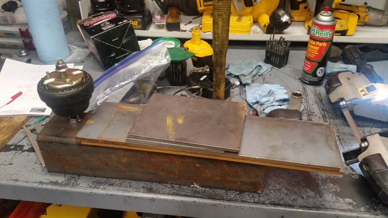
I bent up the brackets and turned the mounting bosses:
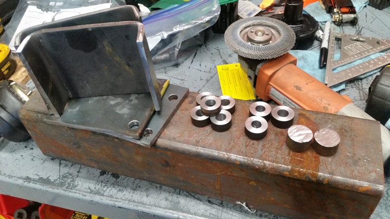
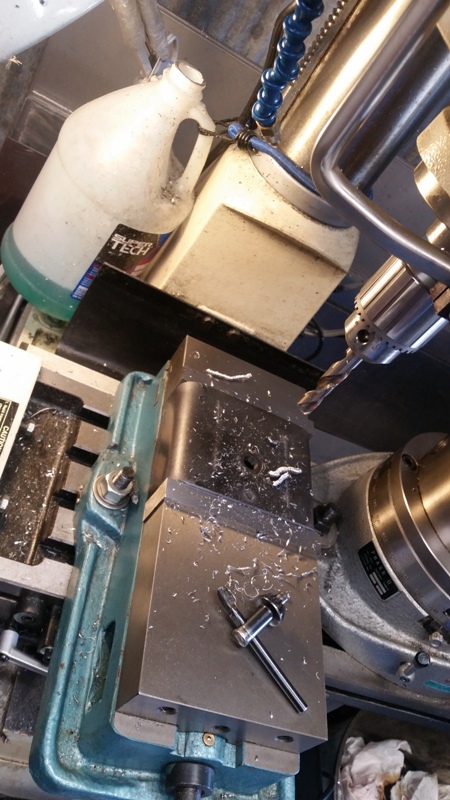
Drilling holes:
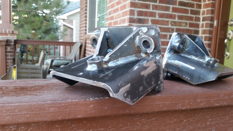
Welded up. Certainly not my best work, but functional:
Painted and isolators thrown on:
On to the frame brackets:
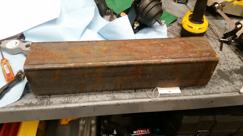
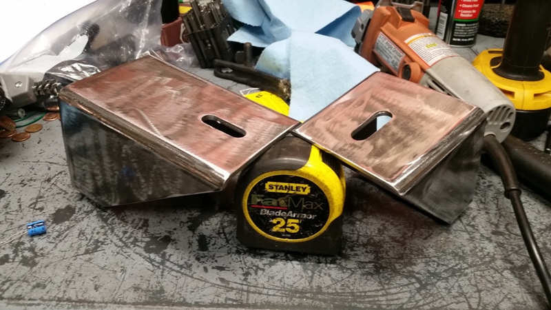
Finished product:

Re: Digger's '69 Build Thread
Posted: Wed Oct 16, 2019 11:30 pm
by Digger
Tonight, my friend came over and we began the 1st engine fitup. First up was getting the Cummins off its shipping pallet:
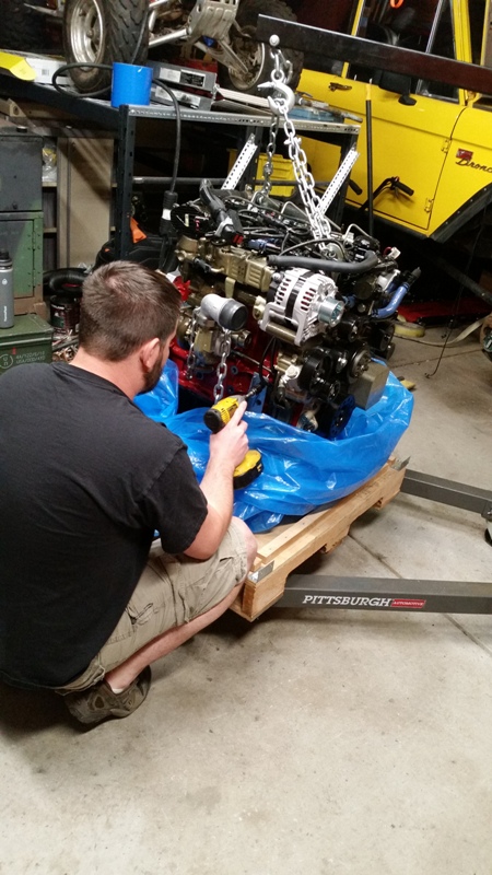
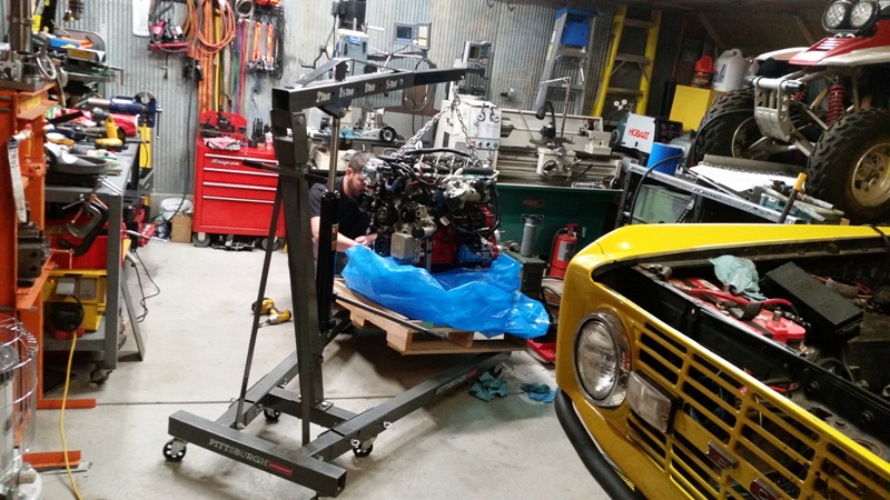
Then we bolted up the motor mount brackets for the first time. They fit like a glove. CAD + CNC = AWESOME
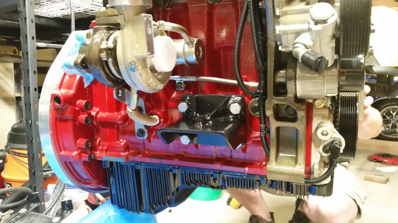
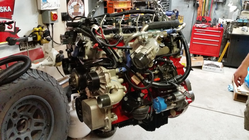
IN YOU GO!
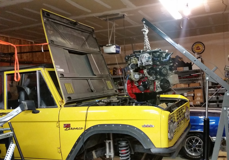
A LOT occurred in this time-frame. We removed the clutch to speed the install. A load leveler would have helped, but our loaner unit disappeared with another friend, so we made due. Fit going in was tight. I needed to pull a few things out of the way, but they needed to go anyway. I was floored, the CAD model match nearly perfectly. The hundreds of hours spent modeling the frame, body and suspension was paying off. We knew every place to look for clearance issues and everything was as the model predicted. It is a tight fit to the firewall, fenders and brake booster/master cylinder, BUT it does fit.
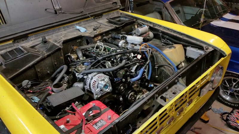
After a beer break and tacking the frame brackets in place, we spent an hour comparing the model to the real deal, checking clearances and looking for problems.
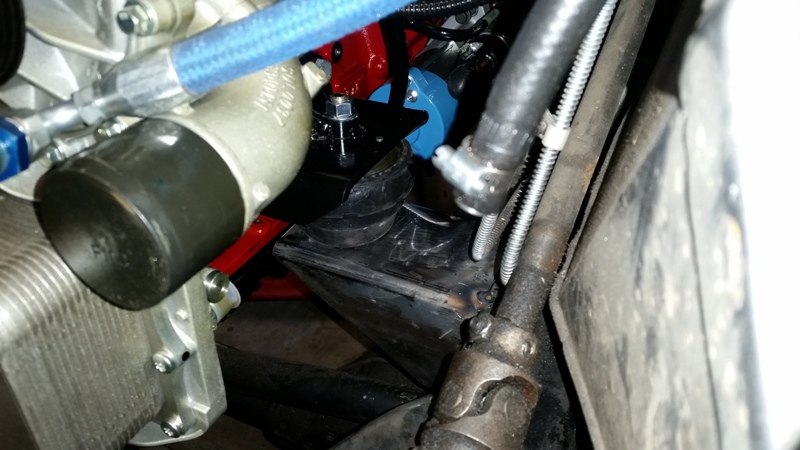
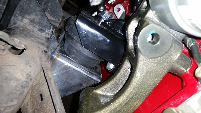
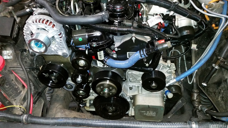

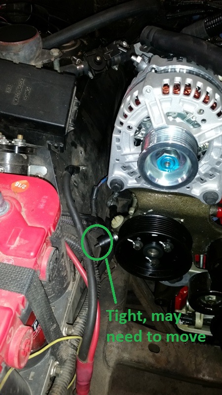
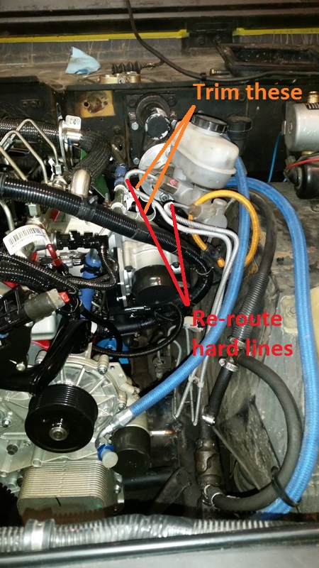
The power steering inlet may need to be moved or clearance:
The CAD model predicted a fit issue with these brackets. It looks like they need to go:
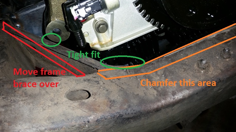
Crossmember clearance was another anticipated issue. Some trimming and sculpting will have to occur here:
One area that showed a problem was hood clearance. I was a little unsure if this was accurate, but as it turned out, we can't quite close the hood fully:

This was the worst problem, but not the end of the world.
Re: Digger's '69 Build Thread
Posted: Wed Oct 16, 2019 11:38 pm
by Digger
One happy result was the axle clearance. Unlike the 351 with Milodon oil pan, the axle completely misses the Cummins pan. They pass right by each other, instead of one gloving over the other. Now this only works because I have full width axles, placing the differential 3" to the driver's side. Otherwise, uptravel would be severely limited. As it is though, I have 7.5" of upward clearance.
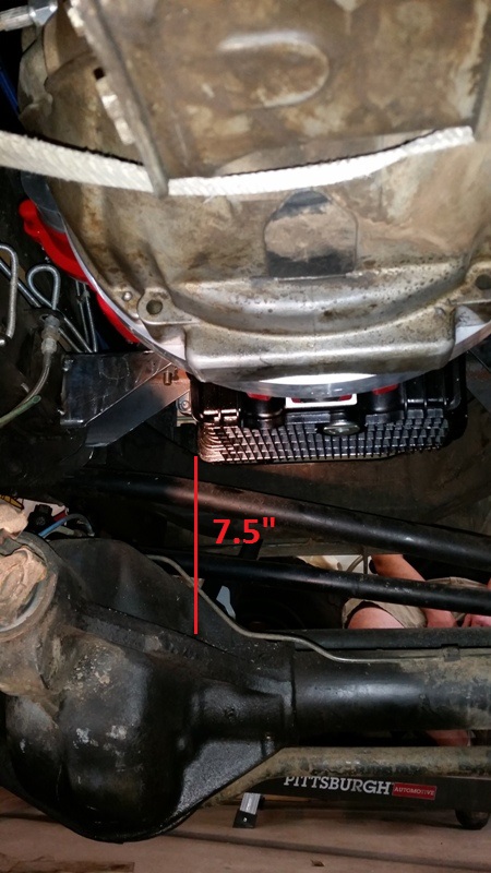
The shape of the oil pan is much better than the Windsor block stuff. Trackbar and drag link clearances still look good. And I'm excited to have a drain plug that points straight down instead of dumping on the axle or crossmember. It's the little things in life...
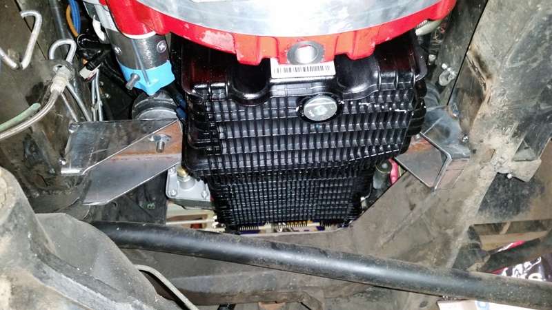
Buttoned up for the first time in nearly a year:
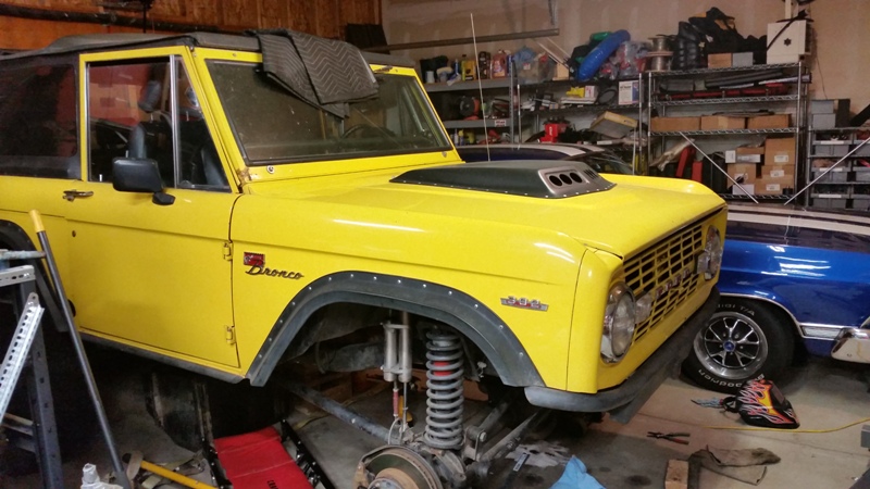
Misc shots:
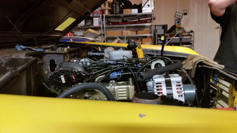
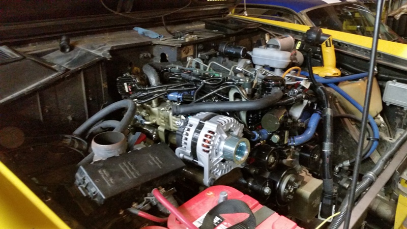
Next steps are to pull the engine back out, weld up the frame brackets, modify the crossmember, clean up the engine compartment and replace the steering column.
Re: Digger's '69 Build Thread
Posted: Thu Oct 17, 2019 8:09 am
by Jesus_man
So much amazingness!!! I wish I could be there to help you thru this, or at least hand you beers!!
Re: Digger's '69 Build Thread
Posted: Mon Oct 21, 2019 5:21 am
by Strike2
Glad to here you've been working on the build, the motor/fab work is awesome!
Re: Digger's '69 Build Thread
Posted: Sun Nov 17, 2019 9:17 am
by Booger
Very nice. It's cool to see this build progress. Can't wait to see it firsthand.
Digger's '69 Build Thread
Posted: Thu Dec 05, 2019 4:29 pm
by Kinder
So excited to see progress on this, do you have an idea of when you think itΓÇÖll be on the road?
Also, did you leave the transmission in the same position that it was with the SBF?
Re: Digger's '69 Build Thread
Posted: Sun Dec 08, 2019 3:45 pm
by Digger
Not sure on timing. I'm down to plumbing and wiring, but there is a lot of details there and I'm hitting a lot of road blocks with this small engine compartment.
Transmission, transfer case and driveshafts are all exactly where they were. They didn't even get disconnected. The R2.8 with my adapter is the same length at the 351W and fits best in the V8's former position in the engine compartment. The bellhousing face in the same on one end and the crank accessory pulley is in the same place on the other end.